A short history of the compass
development is
given here in
Miscellaneous/History. You will find more technical details about ships
compasses in the excellent book COMPASS,
A Story of Exploration and Innovation
by Alan Gurney (W.W. Norton & Co. NY, 2004) - For more books,
see also Miscellaneous/History &
Bibliography. Concerning modern
ships compasses, go to the website
of the Hong-Kong company AMEE & Co. : NAUTICAL
COMPASSES.
Pic. at r.: view of ship's
compasses in a British encyclopedia (1826)
- A -
ACD422 is the designation of a compass
built in a cylindrical casing. The only information available are the
unusual
markings (see pictures below).
Manufacturer unknown
(thank
you for helping with any clues!).
Apparently a
part of a
periscope
compass,
where the main compass is mounted on the flying bridge, above the main,
covered bridge, and where it is read from below through a periscope.
Description: divided circle of the card visible on both sides
(compare to
tell-tale
compass). North
reference symbol: fleur-de-lis. Magnetic
needle: two bars. Card: equipped with float.
Pictures courtesy
Hugh ...
Click
on the pictures for enlarged views)
|

|
|
Technical
Data
Dimensions (height x dia.):
5 x 4-1/2" (130 x 110mm)
Markings:
- Top: Binnacle WD 150 Gauge
- Bottom:
Dia. of shoulder: 31191
Dia. of seating: 33148
- Side: ACD422
|

|
The Admiralty was a department of the Royal Navy (see WIKIPEDIA)
created in 1842.
The history of the Admiralty's Compass Department is
thoroughly
portraited in the book
Steady
as she goes (A. E. Fanning,
1986). It was headed by a
Superintendent
of Compasses.
The most famous ones were Johnson, Creak,
Chetwynd, Creagh-Osborne etc.
This dept. was also responsible for the aircraft
compasses
of the Naval Fleet until WW1.
The Board of Admiralty was abolished in 1964 and its functions
integrated into the Ministry of Defence.
See also the Admiralty's
Pattern
Numbers.
PROFILE - Former U.S. manufacturer (more information
HERE).
See also pocket and
lapel
and wrist compass.

(Click
on the picture
for an enlarged view)
Pictures J. Houcke
|
 |
No.
92 Course Monitor (1958) - Technical
Data
- Dimensions (height x diam. basis) : 5 x 4-1/2" (13
x 11
cm)
- Weight : c. 1 pound (500 gr)
- Serial no. of parts: P-4549 and P-4551
- Divisions: no divisions and cardinals but only the six
letters (every 60 deg.) ABCXYZ. The Y points North.
The pointer's position can be adusted within +/-30°.
The abbreviated axiis are engraved on the base rim: NS and EW
for North-South and East-West in a 90 deg. angle. (Copies of
description and advertisement available on request).
The normal compass was called NAUTILUS (no. 90).
NOTE:
This
item was meant to be used in addition to the normal compass.
As
soon as the boat was on course, the index pointer was set on the
nearest letter representing thus a target easy to follow.
|
Hermann (Hubert Josef) Anschütz-Kaempfe (*
3 October 1872 in Zweibrücken; †
6 May 1931 in
Munich) was a German scientist and the inventor of the compass gyro
(called
"Kreiselapparat"
in his
patent no. 182.855, issued 27 Apr. 1904). The
company Anschütz
& Co. was created
on 28 October
1905 in Kiel and taken over by Raytheon in 1995 (source City Archives,
Kiel, Germany).
Since this device is a
gyroscopic and not a magnetic compass, we do not deal with it in this
museum (see also Sperry pat. 1,279,479).
Concerning the magnetic compasses for German WW1 submarines,
go to
U-Boot.
The French newspaper
La Croix wrote in 1907 that the
system could not work. A few years later, the German submarines were
quite successful...

Labels on binnacle and connectors box
(Click
on images for enlarged views)
Fotos A. König
|
Compass
and binnacle


|
Technical Data
Dimensions
- Height of binnacle: 1080 mm
- Dia. of compass: 245 mm
- Dia. of base plate: 380 mm
- Markings: Eagle and svastika of the Kriegsmarine
(during Germany's IIIrd Reich) above the Marine's 'M' and left
of
the S/N:

|

German manufacturer (See also Wrist and Marching compasses -
more information
HERE).
Its
3-letter-code during WWII was
bxx
(
click
on link for pic. courtesy J-L Rosoux.
The
central part marked ASKANIA came
probably after WWII in replacement for a part bearing the nazi eagle
and svastika).
Picture
at right courtesy
J. Hessels
The first Askania compasses are identical to the Carl
Bamberg instruments, only the designation varies. In the following
catalogues different abreviations are used. It is not possible to show
the complete scope. The figure represents the card's
diameter in mm. Pictures of compasses in the table below are
taken from the catalogues "Nautik 35 and Nautik 36" and also from the
catalogue of Askania VEB Teltow.
In 1954, due to the existence of ASKANIA West Germany (FRG), the plants
in the communist East Germany (GDR) were renamed into
VEB
Geräte- und Regler-Werke Teltow
(
VEB
GRW Teltow - 2nd row in table
below).
3rd row: This is not a compass but a
pelorus.
 |
 |
 |

Cards for dry card and for fluid-damped compasses |
|
Askania - VEB TELTOW (former GDR, inside
pages) |
 |
 |
 |

(Click
on the pictures for enlarged views)
|

Pictures
courtesy Holger "beutelbuch*de"
|
 |
PELORUS
Technical
Data
- Dimensions (L x H): ca. 200x200mm
- Diameter of base disc: 150mm
- Weight: ?
- Manufacturer: Askania VEB (East Germany) between 1948-1954
This instrument was usually installed on both ship's bridge wings.
|
 |
 |

A Ludolph gyrocompass
Pictures
courtesy
A. H. |
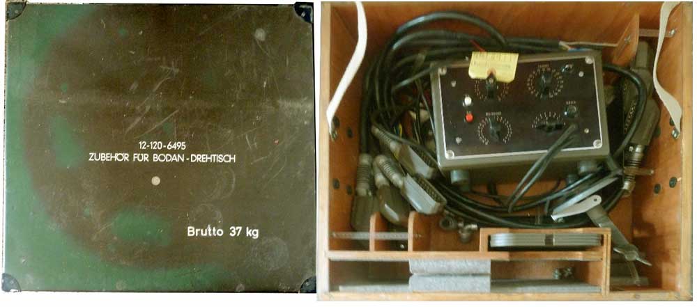
Tester for
gyrocompass
- Manufacturer: BODAN / Perkin-Elmer (after take-over of ASKANIA's
plant Bodenseewerk, West Germany, in 1955)
- NSN: 4920-12-120-6495
- Tools: s. pic. below

|
 |
 |
Link to pic of Prüfschein (control report) |
Bootskompass
Nkl 30 (1943)
- Dia.: 62mm (48mm w/o ring); Height: 35mm
- Read more details in the article U-Boot

|

|

|

|
Bearing compass
with transparent capsule and wrist strap
fittings
Ext. markings: none
Divisions: 360°, written by hand (prototype)
Dim. (w/o vanes):
- Diam.: 2" (50mm); Height: c.1" (22mm)
|
Double Compass For Earth Magnetic Measurements at Sea
 ASKANIA
built for the Deutsche
Seewarte a special compass based on Bidlingmaier's
design. This
instrument was used for measuring the earth's magnetic field from a
safe distance of the carrier ship and at a depth where seaway is not
felt. The relative positions of the cards were recorded by means of a
system of prisms and a camera. The divisions on the upper card were
printed on its underside and both cards illuminated by a lamp
placed between them. The results were published in 1941 in a report for the Deutsche Seewarte (Engl.
translation available) ASKANIA
built for the Deutsche
Seewarte a special compass based on Bidlingmaier's
design. This
instrument was used for measuring the earth's magnetic field from a
safe distance of the carrier ship and at a depth where seaway is not
felt. The relative positions of the cards were recorded by means of a
system of prisms and a camera. The divisions on the upper card were
printed on its underside and both cards illuminated by a lamp
placed between them. The results were published in 1941 in a report for the Deutsche Seewarte (Engl.
translation available)
Technical Data
Card dia: 110 mm
'Antriebswerk '(motor) and dotted line: motor transporting
the film down to the mirror
Click
on the image for a view of the instrument inside the immersion device
|
Photograph of Double Compass
Readings

|
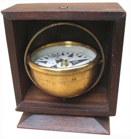
August Augsburg
was a Danish compass maker of Copenhagen (KJØBENHAVN). The
entry for 1826-1862 in the future data base “Sejl- flag- og
kompasmagerlavets
arkiv”
(archive of guild
of sails, flags and compass makers) might
contain some info (
email
sent by Tobias Reinel of the city's archive
office).
Family
data found
in churches'
archives.
The
wooden casing
(height 115mm, Ø 160mm)
Pictures
by courtesy of Th. Steffen |
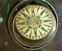
Rose Ø
105 mm
|
Augsburg's
signature inside the compass:

Pic at right: View of an early
compass rose (1850 ?) published in Der
Kompass (1911 - for details go to menue pt. Miscell. /
Hist.-Bibliogr.) |
 |
System used for
compass adjusting (
link to a specialized website).
Examples: C. Plath, London Polaris Pelorus
- B -
BAGAT
(
link to pic)
was the name of a compass utilized in the Yugoslavian Navy. It is
described in the 1964 manual
MAGNETSKI KOMPAS.

Carl Bamberg was a German compass manufacturer located in
Friedenau
near Berlin (for more information click
HERE).
The
company merged in 1921 with ASKANIA (above). Other products: see also
Pocket and Aeronautical
compasses.
The catalogue
Nautik
XVII
(pic at right) describes compasses and binnacles (see table
below). Another catalog (link to pic.
Nautik
XIX) describes the
Instruments
necessary for determining the magnetic forces and swinging the
compasses, especially
the
magnetometer.
Submarines (U-boote) were equiped with Anschütz gyro-compasses
but
for more safety a conventional compass was also installed on-board. See
specific entry
U-Boot.
Concerning type M 414 the following explanation was published on the
web site
warrelics.eu by
drmessimer
:
"They
were introduced into the
Kaiserliche-Marine in 1908 and were
installed in four early Körting engine U-boats, U-1 to 4.
Starting
in 1910, only one and three axis gyro-compasses were installed in the
U-boats under construction (U-5 to 15) and all subsequent boats until
the end of the war. No magnetic compasses were installed in U-boats
that were launched after 1909"
(source: Arno Spindler, Der
Handelskrieg mit
U-Booten, Chapter 10 - Das U-Bootsmaterial. Die
militärisch-technischen Vorbereitung und Vorbedingungen
für
den U-Bootskrieg, pp. 78-94, E. S. Mittler & Sohn, 1932). They
were
installed in surface craft throughout the war, but not used
as the primary navigating compass."
DRY
COMPASSES
Model Ktp250 -
Thomson-Type Rose
(Compare to Hechelmann's design, see also Kelvite)

|
Cards signed by
BAMBERG used by the German Imperial
Navy (1871-1918)
See also the ASKANIA catalogue above.
 
|
|
"Großer
Normalkompass" (large standard comp.)
Ktp 200 and "kleiner Normalkompass" (small standard comp.) Ktp 115
(called
Bootstrockenkompass) *
Technical Data Ktp200 / Ktp115:
- Weight (with parts): 17 kg / 5 kg
- Diam. rose: 200 mm / 115 mm
* NOTE: Designations vary in the catalogues |

 |
The compass Ktp200 was supplied with two roses
comprising each four bar needles: flat on the one, and vertical on the
other (see below)
Note: the rose of compass type Ktp115 only had two needles.
|
| Rose
of winds featuring
the German Emperor's crown below the fleur de lys |


|
Rose
with vertical bar
needles

|
FLUID
COMPASSES
Francis Barker & Son was a British manufacturer (more
information
HERE
and in our LINKS).
See
also Marching, Escape, Pocket, Survey and Wrist compasses.

Catalogue for the year 1930
All
photographs
by courtesy of TradeMarkLondon.com |

Comment: This compass is a very rare item. It was made by Francis
Barker during his apprenticeship when he was 15. His signature on the
card underside and even his fingerprints on the balancing wax can be
seen. Read the full story here: TRADEMARKLONDON.com |

Liquid and dry-card steering boat compasses in slide lid oak box - 1st
half of 19th C.
Technical Data
- Bowl and rings: brass
- Point: steel or iridium
- Cap: sapphire or agate
- Diameter (card): avlbl. from 3 to 8 in.
|
Professor Peter Barlow (Royal Military Academy) designed in
1819 a disc-shaped device representing the metallic mass of a ship and
which was placed near the compass to correct it. It was not as good as
Flinders' bar but was installed for many years in ships during the 19th
C.
PROFILE - Former French compass maker located in Marseilles.

Picture
courtesy
Jaypee - Musée de la Marine, Marseille |

Detail view
(Click
for enlarged view)
|
Technical
Data
Built ca. mid 18th C.
- Divisions : rhumbs - see CARDINALS
|
French company, Division of AMESYS - see Bianchetti below
Former French company created in 1826 and located in
Marseilles also known as Ateliers Julien.
Partly taken over by
BEN (Bianchetti Electronique Navigation) in 1962.
|
Ø 26 cm, Paper mounted on
a mica substrate
Picture by courtesy of T.
McDougall
|
Card: compare to KELVITE
Pic courtesy Jaypee
|
Technical
Data
 |
Friedrich Bidlingmaier (1875-1914) was a German geophysicist
(see Wikipedia in German).
He designed for the German South Pole Expedition
(1901-1903) a special instrument called
Doppelkompass (double
compass,
link
to a short descr. given in a lecture printed in "Meereskunde").
The working principle is thoroughly described in the proceedings of
the expedition (
Der Doppelkompass, Theorie
und Praxis). The first apparatus was designed and
built together with the German compass maker C. BAMBERG (
see above) in the
summer 1906.
This
compass
type comprises two roses placed one above each other. When there is no
exterior magnetic field the N and S ends attract each other and the
needles are parallel in opposite directions. On the contrary, if a
magnetic field is stronger than the earth's field, they both point to
it in the same direction. A different field will cause the roses to
rotate and stop at a proportionnal angle. Several studies had been
conducted since the mid XIXth c. with compasses featuring a
very
small upper needle by
captain Walker,
E. Dubois (
links to drawings)
and also by
F.I. Samkart.
These projects were abandonned due to errors and poor results and
forgotten. Adolf
Heydweiler
rediscovered the principle in 1898 but he gave
up his efforts before achieving satisfying results although he was on
the right way writes Bildingmaier. The latter decided to
conduct
tests and perform measurements with the best roses available at the
moment, namely the ones manufactured by William Thomson (Lord
Kelvin)
and Hechelmann (
see
below).
This compass was also part of the scientific equipement carried on
board of the NORGE airship used for the flight of Amundsen and
Nobile to the North pole (1926) and also for the
flight above
the Arctic of the LZ 127 Graf Zeppelin airship (1931). On one
of
thes occasions the roses were replaced by slimmer ones (s. pic. below).
The German institute for hydrology and meteorology (
Deutsche Seewarte) also
had a double compass built by
ASKANIA
in 1941.
BUSCH
(link zu Survey comp.)
developped a compact version of it in the summer1944.
Click on the images
for
enlarged views
|
View of the roses (at left the lower rose marked Carl
Bamberg) and their eight magnets each
|
The two pivots in the cylindrical container
|
Technical
Data

The original instrument kept at
the GeoForschungsZentrum observatory in Niemegk,
Potsdam
(GFZ) near Berlin, Germany.
The roses were replaced by others, more arrow and easier to
read.
(Picture
courtesy C. Lüdecke)
|
Binnacle
Description
given in a late 19th c. book:
A
binnacle is a waist-high case or stand on the deck of a ship,
generally mounted in front of the helmsman, in which navigational
instruments are placed for easy and quick reference as well as to
protect the delicate instruments. Its traditional purpose is to hold
the ship's magnetic compass, mounted in gimbals to keep it level while
the ship pitched from waves. A binnacle may be subdivided into sections
and its contents typically include one or more compasses and an oil
lamp or other light source. Other devices such as a sand timer for
estimating speed may have been stored in the binnacle as well.
Examples
of antique systems are displayed in the entries: DENT, KELVIN, PLATH.
The Carl Bamberg catalogue
Nautik
XVII and the catalogue
Nautik
35 (1930's) published by its
successor Askania
describe several models of binnacles: type
Khp200, Kh225 etc. (c
lick
on the
links DATA
below to display cutaway views).
The German Navy (
Kriegsmarine)
defined during WWII a common standard system
called
Marineeinheitskompassstand.
|
|
|
|
|
|
|

At left: binnacle with a LUDOLPH compass (above) |
The
compensation
device
|
Marineeinheitskompassstand
Technical Data
View dismantled

Pictures
courtesy Jaypee
/ German Navy
Archives
Click on images for enlarged views |
The French inventor Ernest
BISSON was granted in 1878 a
patent
(no. 124,429 -
link
to p. 1 & 2)
for a system that made it (theoretically) possible to transmit to
"slaved indicators" akin to the telegraph, the
information
delivered by a "master compass" located in a place on a ship where it
wouldn't be disturbed by metallic masses and electromagnetic fields.
One can consider this invention as a predecessor of Albert
PATIN's
remote compass (
see aeronautical compasses).
To this aim, BISSON proposed to use a compass fitted with a
two-ring circular
magnetic needle (
link to pic) of the
DUCHEMIN
type (
read the article
below).
On the outer ring, each division (degree or half degree) would
be
deeply engraved and filled with an insulating material. Two
contacts shaped like tiny wheels located at the end of balanced levers
would roll on the rings (
link
to figs).
These are part of an electrical circuit supplied by a battery and
directed
perpendicularly to the needle so as not to disturb it. One wheel would
roll on the inner ring and the other one on the outer ring where the
insulating material would interrupt the circuit at each crossing of a
division. These signals are then transmitted to electromagnets which
convert this information into movements via two clock mechanisms
(anchor escapement), one for each direction of rotation. This movement
activates indicators (compass-like displays in binnacles or pointers on
scales "like a barometer"). Moreover, each change in the direction of
rotation is detected by a tiny "blade" located above the needle centre
and which is also integrated in an electrical circuit. This blade is
coated on one face with insulating material so that the circuit is
interrupted or closed each time the rotation changes (CW or CCW).
For a copy of the complete document ask the curator (CONTACT button).
Boxing
the compass
"
Boxing the Compass" (
link to the
entry in the Concise Oxford Dictionary) was a basic skill
of any sailor,
being the ability to repeat all 32
points of the
compass (in
¼
points), a 'point' representing an angle of 11¼
degrees. Modern compasses are divided into 360 degrees, 0 (or 360)
being North, 90 East, etc. (
read
more explanations HERE).
This is a part of the
compensation.
Young
sailors learning the
winds
 |
Training
Center, Great
Lakes, 1948

|
Funny
way of seeing
things...

|
BREMEN is
the name of a German harbour of the Weser river.
Several ships bore this city name especially a
sail-steamer launched in 1858
(
link to Wikipedia)
which travelled between New York (USA) and Germany. The famous
scientist
William Thomson (Lord Kelvin)
was granted about 15 years later a patent for a very
light compass rose one of which is known to feature the coat of arms of
the city of Bremen for north in lieu of a lily or a maker's logo. Il se
pourrait que ce compas ait fait partie de l'équipement de ce
navire ou de son succcesseur.
|
Pictures by courtesy
of BSH
|
Click on images for enlarged views
|
Coat of Arms of Bremen
|
Technical Data
Dia. of the rose : abt. 200 mm
Thomson-type rose with 6 magnets
|
BSH
See
Deutsche
Seewarte.
Profile: See Pocket and Marching compasses. This compass is not
gimballed. It is more probably designed for use in a land vehicle.
|
Picture by courtesy of alibabroc
|
Click on the images for enlaged
views
|
|
Technical Data
Dia. base plate: 130 mm
Height: approx. 90 mm
Dia. compass: 60 mm
Dia. cowling: approx. 110 mm
The eight copper springs ensure an inductive damping of
the oscillations.
|
- C -
Louis Pascal [formerly Luigi Pasquale]
(1812–1897)
Casella was a British manufacturer of scientific instruments.
See also Pocket and Survey compasses.

|
L.
Casella's
Catalogue (c. 1876)
Open at the pages showing the SHIPS' COMPASSES.
Picture courtesy Michael Curtis
(Click
on image for full screen view) |

CASSENS was a German company founded in 1902 by Captain Tanne
Janssen Cassens and a partner called Bennecke. It was a retailer for
nautical materiel and was located first in
Bremen,
Tannenstr. 32 (later Sorgenfrei 39-40) and now in Bremerhaven, Am
Lunedeich 131. In 1908, Theodor
PLATH
took a participation in Cassens and the name was changed to Cassens
& Plath. In 1962 bought Cassens C. Plath.
Picture
of a compass
displayed on the header of CASSENS & PLATH's website
.

|

(Click
on the pictures for
enlarged
views)
|
Technical
data
Description of the logo: read the chapter dedicated to C.
PLATH.
The tell-tale compass at right features another logo. Year of
production unknown |

|

Charles Gerard Conn, a famous instruments
manufacturing company was caused to retool its
manufacturing during part of the war years. The identification
plate reads:
U.S. Navy - Bureau of Ships
Mounted - Compass
Mark I Serial __(blank)__ - 1943
Mod O Cont. NXSS-36876
C.G. Conn, Ltd.
Elkhart, Indiana. (Read more info HERE:
www.conn-selmer.com/en-us/our-brands/cg-conn).
Picture
courtesy P. Barnett

Click
on image for view of the
compass rose |

Screws
for the adjustment of the
magnetic deviation
|
Instructions for the correction (see the table under
the
window, on image at left) |
Technical
Data
- Dimensions
• Height: 5.25" / 133 mm
• Depth: 3.25" / 83 mm
• Width (incl. knob-like protrusions): about 8" / 230
mm
- Weight: 7.5 pounds / 3 kgs
Pictures
Don Calanese
|
Captain Louis Wentworth Pakington Chetwynd (b. 15
December 1866, d. 18 April 1914, Coombe Neville,
Kingston-on-Thames, Surrey) was Superintendent of the Compass Dept. at
the
Admiralty
during the early 20th C. He resumed the work of other
inventors (see Crow, Creak) and patented several compass
systems
(see also Wrist compasses).
Among his improvements was the design of a smaller compass card in the
bowl. This solved the problem called the "swirl error" caused
by the moving liquid during quick movements (like course
changes and heeling) of the ship. He became 1912 managing director with
Dent & Co. and Johnson Ltd.
See
also Marching and Wrist compasses and also WBT.

(Click
on the pictures for
enlarged
views)
|

|
Technical data
..
Drawings at left: A. Schück, Der
Kompass (1911)
|

(Pictures by
courtesy of Aaron Chetwynd)
|

|
 Bearing prismatic compass with integrated electrical light. The patent
no. 25,965 was issued in 1906 when Chetwynd already was a retired RN
captain and refers to a gimballed
mariners' compass (link
to pic.)
Bearing prismatic compass with integrated electrical light. The patent
no. 25,965 was issued in 1906 when Chetwynd already was a retired RN
captain and refers to a gimballed
mariners' compass (link
to pic.)
Dimensions
Dia.:
Overall height:
|
Chinese compass, XIXth C. Description given by J.
Klaproth in
Lettre
à M. le Baron A. de Humboldt,
p. 103 and foll.,
online
HERE):
"The 24
Tcheou
(rumbs
or steering directions)
consist of the twelve signs of the
12-signs-cycle*, eight of the 10-signs-cycle** (see below) and
four of the eight
kua"
(trigrams, see Compass types / Religion-China).
* (Usual on
Japanese
compasses)
**
Note: Klaproth marked
these with an asterisk (* - see table below). The two
signs used are
Ki (..?) and Wo (...?) .
The Wikipedia entry
Earthly
Branches
explains the twelve directions as being related to astronomical
observation of Jupiter's orbit cycle almost equal to 12 years which are
used for the Chinese units of time.

Picture Jaypee -
Musée de la Marine, Paris
(Click
on images for enlarged views)
|
Technical Data
Dimensions
- Diameter: c. 150mm
- Height: c. 100mm
- Divisions: 24 Tcheou
(See also menue points MISCELLANEOUS
Cardinals / China
and also
Compass types / Religion / Chinese
Tradition)
|

Table: the 24 Tcheou.
(Klaproth,
Lettre à M. le Baron A. de Humboldt)
|

The ten celestial stems
(Book
? - Appendix A.III)
|
Clement Clarke was a famous British optician who
built
microscopes and various diagnostic equipment. The company was
established in 1917 (Wigmore Street, London). Clarke
signed Mark
VI pocket compasses* probably manufactured by F. Barker & Son
or
some other compass maker like Dennison during WW1. In 1986 the
group was acquired by Boots Plc and in 1989 was purchased by the Swiss
based company Haag-Streit AG located in Berne.
* See
www.compasscollector.com
|
|
Technical
Data
Dimensions (approx.): 150 x 150 x 70 mm
Additional instruments: two levels, clinometer in the lid,
- Sighting vanes: two vertical tabs with a pin-hole each in
the left and right
case walls. A foldable two-piece telescope.
Centimeter ruler on the
lower front
case wall.
NOTE: This bearing compass is a (worthless) contemporary
reproduction (see MISCELLANEOUS
/ Fakes). One can tell this by some details like the magnetic
needle's
bright red
point
and the green central jewel in the cap. The clinometer's
arrow point is also at
least very unprecise. It is highly improbable
that Clarke ever produced such an antique
C.19th instrument.
(Click
on the image at left for
an enlarged view)
|
Compass,
Testing Laboratories
By virtue of the international convention for the Safety Of Life At
Sea,
SOLAS,
Ch. V, Reg.
19.2.1.1), the International Maritime Organization
(OMI), an agency of
the UNO requires the following:
Shipborne
navigational equipment and systems All ships irrespective of size shall have: a
properly adjusted standard magnetic compass or
other means, independent of any power supply to determine the ship's
heading and display the reading at the main steering position;

In
Germany,
the testing activities of magnetic compasses is one of the
responsibilities of the
Bundesamt
für Seeschifffahrt und Hydrographie, BSH
(Federal Maritime and Hydrography Agency) in Hamburg, successor of the
Deutsche Seewarte. The
office specifically in charge of this task is the
Magnetkompasslabor
is situated in a small building built in 1950 on top of the
hill
where
the former castle of the Seewarte destroyed in 1943 stood. It
is
especially protected against all magnetic
interferences by
means
large-sized coils (
link to a sketch).
These coils also make it possible to simulate any terrestrial magnetic
environment. The labor comprises all sorts of test equipment (see table
below) and also a small museum (
not open for visitors).
The
compass laboratory in 1950
(in the background at r.: Bismarck's statue). It is today
concealed by trees *
(
*
screenshot
Googleearth).
Pictures by courtesy of
BSH (Click on the
images for enlarged views)

Measuring the intensity of magnets with a special BUSCH
magnetometer (placed on
the
central rig). Link
to user instr. (1943).
|

Inside view - at centre :
large rig for measurement of electromagnetic interferences
|

Dimensions check rig
|

Test rig for viscosity check of fluids when rotating
|

Thermal test chamber |

Vibration test on horizontal and vertical axii. |

Test rig for tilting and rotating together with binnacle |

Test rig for rotation when tilted |
In
Great-Britain,
the
Compass
Observatory of the
Admiralty
was in charge of this task. See also the regulations of the Maritime
& Coastguard Agency.
In
France
and in many countries the organisation called Bureau
Veritas is entitled by the governments to perform the control of
compasses.
In the
Unites
States of America
... (
no information
momentarily available).
Compass
types
There are many different compass types: the large gimballed
compass
integrated in a
binnacle
and the smaller removable
dory compass
in a wooden box (ex.: VION), not to forget the overhead hung
telltale
compass. For more precise details about compass functionalities, go to
chap. 2.1
General
Definitions of the
ISO 1069
standard. See also the various
patterns
defined by the British Admiralty.

On metallic vessels compasses are strongly disturbed not only by the
metallic masses but also by the electric cables, motors, engines etc.
The
optimum solution is to use gyrocompasses but in order to counter these
influences on magnetic compasses, several methods are used. In 1894, G.
Dary published a comparison of the light-weight Thomson compass card
and the heavy French concentric system designed by Duchemin
(
see fig. at r.,
read the relevant entries). A very good study is to be
read in
Steady as she
Goes.
Visit also the website
magnetic
compass
adjustment.
The magnetic influences on compasses are exerted along five main
directions called by the letters A, B, C, D et K.
The means used to solve these problems are also designated in the same
way. (
French document
published in 1873:
Notions
sommaires sur la déviation des boussoles par le fer des navires.
- A is the error caused by a wrong alignment of the binnacle on the
ship's deck. Solution: rotate the binnacle vertically.
- B and C are the semicircular deviations. They are caused tby the
metallic masses along the longitudinal and lateral axes. They are
corrected by inserting magnetic rods at various heights in the
binnacle. On smaller boats / compasses, this is done by means of
"spread" magnets which can be moved relative to one another (compare to
aeronautical compasses)
- D is one of the quadrantal deviations. To counter this effect two
movable metallic spheres (red and green) are placed on each side of the
compass. On certain compasses like the spherical models made by e C.
PLATH (called in German Dom- or Kugelkompass), metallic blades (made of
Permalloy, also named Mu-Metall in German, see Wikipedia) replace the
spheres.
They are cut at the desired length and attached by means of a bridge.
- K is the vertical component which causes a dip of the card.
It is counteracted by the very powerful K magnet which is hung in the
binnacle under the compass by means of a chain. The error corrected by
this magnet is the heeling error.
- There is also the Flinders Bar, which is a tube placed before the
binnacle in which metallic blocks are placed. Their height can be
determined by means of wooden pieces.
Link to a video explaining the
various compensation means.
Captain Frank Osborne Creagh-Osborne (1867/1943) was
Superintendent of Compasses (successor of Captn. Chetwynd) at the
Admiralty and a British inventor.
(more details
HERE).
Captain Ettrick William Creak was Superintendent of the
Compass Dept. at the Admiralty. He developed in the 1880's a liquid
compass that worked
better than Sir William Thomson's dry card system but he was
unsuccessful at his attempts to have it chosen as the Admiralty's
Standard Compass because of Thomson's lobby.
Francis Crow was a watchmaker and silversmith of Faversham
(Kent, Great-Britain). He was awarded in 1813 a patent (no. 3,644)
for a liquid-damped compass with a lens-shaped floating card. This
revolutionary
idea was realized only much later (c. 50 years) by the U.S.
manufacturer
Ritchie.
Full text of original patent available.
|
(Click
on the image for
an enlarged view)
|
Technical
Data
Complete description of fig. 1 and 2 HERE.
|
- D -
Go to Dubois & Casse below.
Edward John Dent &
Co. was established in 1814. The company still exists today.
Its
website (www.dentlondon.com) only describes clocks and
watches. See also the Dent-made
Air Compass
Pattern
259 designed by
Capt.
Creagh-Osborne. See more examples in the entry
PATTERNS.
 |
At
left: Early designs
by DENT
and
Harris
Picture
by
courtesy of the National Maritime Museum as published in Steady
as she Goes by A.E.
Fanning, 1986
At right: Portable binnacle Pattern 20, 1875
Picture
by
courtesy of J. Clarke - see more pictures in PATTERNS
Click on the image for a view of the compass.
|
 |

Probably early 20th c.
|

The
Deutsche
Seewarte
was in the late 19th and early 20th C. a department
of the Admiralty of the German Imperial Navy
Kaiserliche Marine
(see below:
Kriegsmarine
and read more
in Wikipedia). Its Second Department
(
Instrumentenprüfung,
testing of instruments)
was responsible for the testing
of navigation instruments, i.e. also compasses, being thus the
equivalent of the British Superintendent of the
Admiralty
of the Royal Navy. Its official monthly review was
Der
Seewart (
link
to the cover of the Dec. 1939 issue).
Today, the responsible authority is the Federal Maritime and
Hydrographic Agency (
Bundesamt
für Seeschifffahrt und Hydrographie, BSH)
located
in Hamburg. The department in charge of the testing of
compasses is the
Magnetkompasslabor.
Picture by courtesy of BSH: The
former castle of the Deutsche Seewarte destroyed in 1943
The full history can be read online here
Die Geschichte maritimer Dienste in
Deutschland - Das BSH und seine Vorgänger (German).
In short: Germany as a unique country was created in 1871. The various
former agencies like the
Seewarte
which had been created on private
initiatives were then united under the authority of the Admiralty in
the
ministry of the Navy. After World War II and until the end of
the
GDR (Communist East Germany) in 1989, a service similar to the
Kompasslabor
existed there, located in Rostock from 1959 on and depending of the
department
Bagger-,
Bugsier- und
Bergungsreederei (dredgers, tugs and salvage
boats).

Since iron-hulled ships replaced large wooden ones (mid 19th
C.) a correction card
was
necessary to steer the vessel by taking into account the magnetic
influence of the metallic masses. For pictures of modern
correction cards click
HERE.
According to the ancient card displayed at
right, the ship would have to steer SW by her compass in order
to make good a course of WSW magnetic (Source: Alan Gurney,
COMPASS,
2004).
Click
on picture at right
for
enlarged
view

The Eugene M. Sherman Company of Seattle designed and manufactured
nautical navigational aides, notably the line of Dirigo gimballed
compasses.
See also Aeronautical Compasses: SHERMAN
Click
on picture at right
for
enlarged
view

Abel Louis Doignon was a French compass maker located 11, rue
Hoche in Malakoff, Paris / France (see also Marching compasses). He
filed several patents for ships' and aircraft compasses between 1905
and 1928. A special one was no. 539.589 of 1921 concerning the use of
tiny
tubes containing Radium salt (
link to pic) and
attached to the rose to evitate that they be destroyed by the
liquids used.
Pic.
at r.: compass produced in cooperation with B.B.T.

Mr. D'ONZEMBRAY described in 1731 a system designed to
determine at sea the angle of the wind relative to the compass and the
ship's keel line (
Machine
pour connoître sur Mer
l'angle de la ligne du Vent & de la Quille du Vaisseau ; comme
aussi l'angle du Méridien de la Boussole avec la Quille et &
l'angle du Méridien de la Boussole avec la ligne du Vent
(published in 1764 in Histoire de l'Académie des
Sciences). The aim was to optimize the trimming of the many sails. The
device comprises a wind vane with a pointer placed
above the compass card featuring degrees and rumbs (
complete descr. available, 5 p.).
Dory compass
See
compass
types

Dubois & Casse was a French maker of
barometers (
link to a
photograph of the
rearside of an instrument, pic. courtesy J. Clarke)
in the second
half of the 19th c. The company's logo was made of the initial letters
D and C on either side
of an anchor. (Source: analogweather.com)
PROFILE - Emile Marin DUCHEMIN (who lived 11, rue de la Bienfaisance in
Paris) filed a patent in 1874 for this compass system he
had developed and called BOUSSOLE CIRCULAIRE (circular
compass). This
device
was installed in ships for several trials at sea
(1873-75) in
the
vessels
described in the booklet (iss.
7, 1877, 47 p., photocopy available). It is also listed the
famous German reference book
Der
Kompass (Schück,
1910). The inventor tried to have his
system adopted by the French Navy and produced many reports from
officers with positive feedback. However, it is highly surprising that
someone clang to this obviously heavy design where the Admiralties of
England and Germany tried to develop the lightest solutions that could
be imagined (compare to the paper rose with magnets hung on silk
threads designed by
Thomson,
Hechelmann
and
C.
Plath).
The idea was that the larger the magnet was, the better the stability
of the rose should be. Read also BISSON's patent.
(Click
on the picture above for an
enlarged view of the drawing)
Short description together with the drawing on the title page: "an
external magnetized circle (A) is connected with an inner magnetized
circle (B) by means of a bar (C) made of aluminum or another metal. The
magnetization is maximum at the North and South points and diminishes
gradually towards the EAST and WEST points (n-n line)."
Pict. at r.: The magnetic circular needle.
NOTE:
this
instrument was in very sad condition. Its remains were glued onto a
marble
grip like the religious tool called monstrance. The photographs
were taken at an antiques shop in Paris. |
Above - Inscription on either side of the North mark: Boussole Duchemin
Bté S.G.D.G.
Bottom - Inscr. at the southern end: Dumoulin-Froment Constructeur
(Click
on pictures
above for enlarged views -
Pictures courtesy Jaypee) |
Technical
Data
- Dia.: approx. 250 mm / 10 in.
- Weight unknown
- Inscriptions on the East side:
. inner circle: N° 1616 E.M.D.
. external circle: Emile Marin Duchemin - No. 1616
Patent No. 101,992 (50
p. with additions - copy can be ordered)

(Click
on pic.
above for a view of the corresponding figure 2 of the patent)
NOTE: A complete binnacle is displayed in the Musée de la
Marine, Paris. See pic. in L'Instrument de Marine,
Jean
Randier, 2006.
|
E - F

A Flinders bar is a
vertical soft iron bar placed in a tube on the fore
side of a compass binnacle (
see
picture at right, KELVIN
compass).
The
Flinders bar is used to counteract the
vertical magnetism inherent within a ship and is usually calibrated as
part of the process known as swinging the compass, where deviations
caused by this inherent magnetism are negated by the use of horizontal
(or quadrantal) correctors.
It is named after Matthew Flinders (1774-1814) who wrote a
report in 1812 on
ships' magnetism for the British Navy.
Read
the whole story in
COMPASS
by Alan Gurney (2004).

Thomas Flint was Mathematical instrument maker, Nautical
instrument maker, Optical instrument maker 9 High Street
(1826-31) and later 31 Whitefriars Gate, then 34 Whitefriars Gate
(1835-48) all in Hull, England. The
instrument at right is a
tell-tale
compass
(pic.
courtesy J.
Spence). Very unusual is the
west-decorated cardinal point of the rose
of winds. Most cards featured an
east-decorated
rose of winds
(link to
special entry).
We suppose that this compass was meant to be used in the Indian Ocean
where Jerusalem lies WEST.
- G -
GALILEO
Transmitting magnetic compass
used in some ships of the Italian Navy in the early 20th c.
The control was provided by a lamp in the bowl which shone through a
semi-circular slot in the card and illuminated a photo-electric cell
above the card, when the latter was in the appropriate position
relative to the bowl, while at other times the light was cut off from
the cell by the solid part of the card.
Source:
From Lodestone to Gyro-Compass
(see menue Miscell. /
History & Bibliography).

GEHNA
Acronym of Georg
Hechelmann
Nachfolger (successors, see their website: www.gehna.de).
The company no longer produces compasses
but binnacles. Link:
pic.
of the last known model.
Pictures courtesy of BSH (click
on the image
for a pic. showing the manufacturer's full name)

Description -
System probably invented by Girolamo
Cardano (Padua
1501-Rome about
1570)
who was among other specialties an Italian doctor and engineer. This
system which was called after him in French and German
(
suspension
à
la cardan / kardanische Aufhängung)
is designed
to compensate for the movements of a
vehicle (ship or aircraft) so that the compass card always remains
horizontal (more details in Wikipedia).
Small compasses were also made for other usage.
Examples :
pocket
compass (N & Z),
tell-tale
compass
(Steward),
box
compass
(N & Z),
miner's
compass,
charm (see picture at right
,
copyright TML, click for enlarged view)
Techn.
Data:
Dia. of spherical case: 19.5mm; dia. of mother of pearl card:
11.5mm; weight: 12 g.
GRW, Geräte und
Regler-Werke
The company Geräte und Regler-Werke was a German manufacturing plant of
equipment and
regulators located in Teltow, successor of the
Askania-Werke AG which built the compasses designed by Bamberg
Friedenau after WW1. The company became state-owned in 1948 during the
communist era in Eastern Germany (FRG, 1945-1990) and integrated in
1954 into the state-owned company VEB GRW TELTOW (Source: Digital
Museum Germany / nat.museum-digital.de).
See also ASKANIA above

Pictures courtesy
nat.museum-digital.com)
Click
on the images for enlarged views
|
 |
Technical
Data
Dimensions (container): 200 x 200 mm
 |
Gyro-compass
/ Gyro syn
A gyroscopic compass is an electrically operated
instrument, controlled and damped either by gravity of electrically so
that the spin axis settles in the meridian. These instruments are not
the object of this museum. The gyrosyn is a remote-indicating compass
system employing a directional gyroscope which is monitored by and
synchronized with signal from an element fixed in azimuth and designed
to sense its angular displacement from the earth's magnetic meridian.
This element, called flux valve or flux gate, is located at
some
remote
point, e.g. wing tips on aircraft, away from
extraneous magnetic influences. (Source:
Chambers Dictionary of
Science and Technology, 1974)
For a picture go to Anschütz above. For a pic. of a test bench
go
to Askania.
- H -

PROFILE
- HANSEN BEARING BOARD
(see picture at right):
go to
PELORUS.
Leendert Johannus HARRI (born 1799) was a Dutch
kompass
maker in Amsterdam. His family (glass maker) came from a place
near Venice (Italy) to Holland in 1730. The company is
known for its instruments, marine charts and literature.
|
|
|
Technical Data
Dia.: approx. 5" (125mm)
Height (with lid): approx. 4 ¾ " (120mm)
Dia. of compass card: 4" (100mm)
|
W. HARTMANN, compass maker located in Hamburg 11. Some
compasses are marked GEHNA (see Hechelmann below) and also NAUTICA. No
information available.
Pictures courtesy of BSH.

|

|

|
Technical
Data
Dia.:
Height

|
Former German compass maker of Hamburg (successor:
GEHNA,
website www.gehna.de) who
patented (D.R.P.
23.503, 1874) an improved
version
of
Thomson's
(Lord Kelvin) design of a paper
rose with magnets hung on silk
threads (see pic. below). He worked in his own shop
from 1.10.1878 on until probably 1905 (source:
Feinmechanik
und Optik in
Hamburg,
Gert Behnke, 2011). A comprehensive description was published in the
entry for
Kompass
in the great German encyclopedia MEYER's
Konversationslexikon.
This system
is also described in the reference books
Der
Kompass an Bord (
Deutsche
Seewarte, 1906) and
Der
Kompass
(Schück, 1911). His competitor
C.
PLATH
also tried in vain to have his own system supported by the Admiralty of
the Imperial Navy (Kaiserliche Marine).

Pictures by
courtesy of BSH
(Click on images for enlarged views)
|
Technical Data
 Dia. of disc: 1. Dia. of disc: 1.
The magnets and their fittings were quite heavier
than Thomson's system and this caused a stronger friction of
the cap on the pin.
Address on the disc: Vorsetzen 3
Link to figs in patents: click HERE
Probably a first or provisional version featured magnets which were
attached directly unter the rose:

|

 Drawing from the
book 'Der Kompass an Bord' (1906)
and photograph of side view published in
Der Doppelkompass
(Bidlingmaier)
|
Description in centre window.
|
Technical Data
Compass made at about the same time as the brigg
Ausguste* built in Wismar
(Germany) in 1840.
Full name around pivot cap in centre: Georg Hechelmann Nachf.
(G.H. successor). "Vorsetzen 15" was the shop's new address in
Hamburg.
*
Mock-up
in the city museum of
Wismar - Picture courtesy
Jaypee
|

The logo 'G.H.' on the rose of winds la rose
(picture
courtesy
D.
Hölber)
|
Petter HOLM was a compass maker located in Copenhagen,
Dennmark (Kjöbenhavn). Several instruments are known.
The webster database Adlerplanetarium indicates for his birth and death
dates 1696-1776. His nationality is unclear: he appears in Sweden,
Dennmark and Holland as maker of tide tables, calenders etc.
He is also said to have headed a navigation school.
We know a compass made in the late 18th c. (repaired in 1804) and a
drawing published in
Der Kompass (A. Schück, 1911, see Miscell. / Hist.
& Bibliogr.). This latter one is signed by RASM. ANDR. HOLM.
Its
short description only mentions
the rose's colours (white on black ground) and where it is
kept (K.I.M. = Königliches
Institut für Meereskunde, Royal Inst. for the sciences of the
sea).
 
(Pictures
courtesy Uwe Münch)
|
Technical data
Dia. x height: 145 x 120mm
Magnet: two under the rose
Date: late 18th c. (repair mention inside: 1804 and Rostock 1817, Evers)
|
  |
 |
North
fleur
de lys on a rose signed by Rasmus Andr. Holm
(a son of Petter?).
Inscription on the 'strap': ANGELO.
The East decoration is also different.
Drawing: Der
Kompass, tabl. 20
|
|

In 1926 S. L. HOLMES developed a successful
transmitting
magnetic compass (TMC) using the principle of the Wheatstone
bridge. It was produced together with BENDIX (Pic. at r. courtesy
INVALUABLE - The instrument is marked E.S.Ritchie Sons Inc. 91270. 1920
Patent. Dim.: H: 6.5": W: 11.5": D: 11.5")
Read the functional description in
From Lodestone to Gyro-Compass
(see menue Miscell. /
History & Bibliography).
Former French company (more information
HERE).
Henri Isidore Houlliot and
VION
were friends and decided not to compete.
VION built the big ship compasses while the small ones
were manufactured by Houlliot.
See also pocket compasses and
DESOMBRE.

Production
scope (published in the catalogue
of the Industrie
Française des Instruments de
Précision,
issue 1901-1902)
|
Large business
card
(130 x 84 mm)
(Click
on img. for
enlarged views)
|
Gimballed compass
(was offered in the 1932
catalogue of the
Société des Lunetiers (S-L)
Technical
Data
- Card dia.: 30* - 120 mm (* see pocket compasses)

|
Henry Hughes was born in 1816 (read all available info
HERE).
Most HUSUN compasses are aircraft compasses but this one seems to have
been designed for ships. Astonishingly the S for south is
inverted, which means it was to be read in a mirror or a prism like the
Creagh-Osborne
compasses. The patent no. refers to the
Campbell
& Bennett invention.
 
Pictures courtesy of Dánial K.
Thomsen.
Click
on the images for enlarged views
|

|
|
Technical
Data
Dimensions (height x dia.): 105 x 255mm
Divisions: rhumbs on both side plus degrees on underside
Marking DEAD BEAT = aperiodic compass (check this word in the section
Aeronautical Compasses)
NOTE: On the compass card with no figures, the letter S (South) is
printed inverted. This means that this side should be located below the
compass to be observed in a mirror. Maybe the compass was dismantled
and reassembled erroneously after a maintenance or repair.
|
- I -
IMRAY
Laurie Norie &
Wilson Ltd London
This manufacturer apparently makes now only charts. His story
is told in the
book
The
Makers of the Blueback
Charts: A
History of Imray
Laurie
Norie & Wilson Ltd by
Susanna Fischer, 2001. Actual website:
IMRAY
 Pictures
courtesy
Menno Koper (Click
on the images for
enlarged views)
Pictures
courtesy
Menno Koper (Click
on the images for
enlarged views) |
|
Technical
Data
Dim.:
- Card dia.: mm
- Age: mid 19th C.
|
- J -

Japanese compasses were divided into 12 areas. Scroll upward to CHINA
for more details.
Picture courtesy of BSH
In 1863 F. Jenkin patented a
transmitting
magnetic compass (TMC) system in which a contact attached to
the card wiped one or other of a hundred contacts spaced around the
bowl. From each of these contacts a wire led away to the repeater, in
which a pivoted needle was placed in the center of a circle of 100
electro-magnets, one of which was energized when its contact was
touched by that on the compass card. The repeater needle, of course,
aligned itself with whichever electro-magnet was energized, so that the
repeater followed the indications of the compass. Compare to BISSON's
system.
Source: From Lodestone to Gyro-Compass (see menue Miscell. /
History & Bibliography)
Lieutenant Edward J. Johnson was the 1st Superintendent of
Compasses at the British Admiralty from 1842 until his death
in 1853.
- K -

The Dutch Prof. Kaiser designed in 1892 a compass rose featuring a
circular magnetic needle attached to the cap via tubes. It was later
improved by the German SCKELL who replaced the tubes with chains.
Compare to the French DUCHEMIN's rose.
Click
on picture at right
for
enlarged
view and details of patent

KELVIN HUGHES
Ltd was formed in 1947 by the merger between
the scientific instrument manufacturing firms of Henry
Hughes
&
Son
Ltd, London, England, and
Kelvin
Bottomley & Baird Ltd, 16 and 20 Cambridge Street
Glasgow,
Scotland. The logos of one of the preceding companies (White,
Bottomley, THOMSON)
consisted of the three initials
WBT
placed on a black & white
graphic resembling the
yin-yang
symbol (s. WBT in the section Wrist Compasses and pic. at
right -
Read
the full
story in
Wikipedia - "Kelvin Hughes" and on the
company's website
www.kelvinhughes.com)
KELVIN is the second name of the physicist William
THOMSON after he was
ennobled to become Lord 1st Baron Kelvin of Largs.
He described an ultra light compass card and an improved binnacle with
compensation spheres on either side in a first patent (no. 1339, issued
29 March 1876) and in its second version issued in the same year (no.
4876, 18 December 1876). Link to image:
click HERE (pictures by courtesy
of the University of Glasgow).
His compass card featured a
360°-scale on the circumference in addition to the conventional
32
rhumbs. It was standard in
the Royal Navy although the superiority of liquid-dampened compass
card was soon proven and adopted in the U.S. and
other
Navies (read the full story in
Compass
by A. Gurney and in
Steady
as she goes by A. E.
Fanning).
Both German manufacturers
C.
PLATH and
G.
HECHELMANN
developed their own version of this system.
Thomson wrote a
document entitled
Terrestrial Magnetism and the
Mariner's
Compass. He
also was partner
in several companies which built the compasses he designed.
See also below, the booklet "
Instructions
for the adjustment etc."
The basic design featuring several magnets hung well below the card was
also applied to smaller cards made of paper and aluminium (see
description
here:
MSP).
The
Thomson/Kelvin compass:
The original light-weight
compass card had eight
magnet needles (M, see drawing at left below) but a later model
improved to prevent
disturbance
of the compass by the engines, or by the firing of guns
(patent no. 4923, 1889) possessed even 14 (pict. below at right)! The
central
part was
cut-away
and the graduated rim
suspended
with 32 silk threads (S) attached to the cap.
More details and pictures in
Land
& Sea Collection.

KATAV-IVANOVSK INSTRUMENT-MAKING PLANT,
JSC ( Катав-Ивановский приборостроительный завод ) is a Russian
manufacturer located in
Katav-Ivanovsk, 456110 Chelyabinskaya oblast, Katav-Ivanovsk, ul.
Karavaeva 45 and producing a large scope of nautical and
wrist compasses
The compass at right is a common Russian naval system for calibrating
naval compasses. The name is "Инклинатор И" (Inklinator 'I'. Each ship
has it's
own magnetic field and a compass must be calibrated for it. But the
magnetic
field direction is not only horizontal - it has vertical part. When a
ship moves to
different places, the vertical component can vary and the change of the
vertical
part of Earth magnetic field can be very important.

A compass for
"everywhere-use" must be calibrated for its own ship magnetic field not
only for the horizontal, but also for the vertical part. For this
calibration, big (main) ship compasses have something alike steel bolts
(magnetic). Original descr. on the manufacturer's website: "Инклинатор
"И" для измерения угла наклонения вектора магнитного поля.
Используется при девиационных работах. Применяется для типов компасов
КМ 100, УКПМ-М, КМ 145.
Производители/поставщики: ЗАО «Катав-Ивановский
приборостроительный завод»
This designation refers to the German Navy after 1935 (see note). When
Germany was united to form an empire in 1871, it was called
Kaiserliche Marine
(Imperial Navy). The compasses used on-board the German warships
featured a symbol representing the state, i.e. the imperial
crown
or the nazi cross (swastika) and the letter
M
for Marine.
The number is the catalogue reference similar to today's NATO
Stock Number.
Note: After 1918 and until 1935, Germany was not allowed to produce and
own war vessels.
At right: the coat of arms of the German Imperial Navy
Techn. data: see BAMBERG
compass
Click
on images for enlarged views
(Picture by courtesy of
Atlantikpirat/guntherprien47)
|
Engraving
on the rear face of a pocket compass which possibly belonged to an
airship's captain during WWI
(see pocket compass BAMBERG).
(Picture at left by
courtesy of
Andrew
N.)
|
1933-1945: Symbol of the IIIrd Reich (Eagle and
Svastika*) and PLATH's
logo, a sailor with a sextant
See description in PLATH below.
* See also ANSCHÜTZ and ASKANIA
(Picture
by courtesy of
Leonardo Signirole) |
 Kuhlmann
(link to this company's website) was created in 1903 in
Wilhelmshaven
(Germany). This instrument used during WW1 to compute the launch angle
of torpedos is called in German
Angriffsscheibe
(attack course finder disc).
Pic. at r. © A. Uhler. See also the same instrument
made by
STEGER
of which we have better quality pics.
Dimensions of the case: 7
1/8
x 13 ¾ in. - 18x32cm