- L -
Additional compass used for
swinging
aircraft compasses. Its use is explained in
The Aircraft Engineer's Handbook (
follow this link)
by Sloley and Coulthard (No. 4 Instruments, 6th ed. 1946). Example: Air
Ministry Type O6A (later models:
Sestrel).
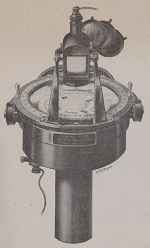
The French company Société des établissements
HENRY-LEPAUTE (11, rue Desnouettes, Paris XVe) was a famous
manufacturer of clocks and watches. It also produced numerous
electrical and optical materiel. This compass type
was patented in 1910 (no. 407.416). Its
characteristic feature is the double pivot. The upper one's length can
be adjusted vertically (see image from Patent below).
Le Prieur
French inventor of a drift computer called
navigraphe (see
NAVIGATION)
Letecke Pristroje Praha
Letecke Pristroje Praha (Aircraft Equipment Prague) was a
Czechoslovakian company located in Prague.
On his transatlantic flight from NY to Paris in 1927, Charles
Lindbergh's aircraft the
Spirit
of St. Louis* was equipped with an
earth induction compass.
He had then made by Longines the
hour angle watch
called after him. (
*
note the T-shaped anemometer protruding out of the fuselage behind the
cockpit)
W. LUDOLPH GmbH & Co. KG (Bremerhaven) is a German
company manufacturing nautical and aeronautical compasses.(more
information
HERE).
Some examples of compasses (FK =
Führerkompass =
pilot compass).
A. J. Hughes writes in his
History of Air Navigation
(1946, p. 34) that the first experiments (dealing with the behaviour of
the compass) 'were made by Keith LUKAS at the Royal Aircraft Factory
(Farnborough) in 1917 and this led to very important results, as the
compass had to be carefully observed and special methods of
damping introduced which minimized the effect of northerly turning
error. The work of Keith Lukas was the most important scientific
contribution made during the 1914-18 war to air navigation' (See
chapter
AIR MINISTRY /
Compass type Mark II).
- M -
 Repeater compass
 invented
by Pioneer Instr. Co. (patent no. ?, in 19xx ?). The system
consists of a transmitter and from one to three indicators as desired.
It has no moving parts other than a compass float and the indicator
pointers. The transmitter unit comprises a liquid magnetic compass,
below which is mounted an electrical pick-off of the stationary
induction (source: A. J. Hughes,
History
of Air Navigation, p. 109).

Alexander G. MARQUIS, a Briton living in Rochester, N.Y. USA,
invented in 1911 a new compass type which was tested by the aviator
William Hilliard in his aeroplane at Mineola, L. I. The needle pointed
south and was observed in a mirror apparently pointing north (see pic.
at right). Full description available, published in
The
Scientific American, March 1911.
On some WWI compasses the maker's name indicated is "
MAUVE Paris"
together with the words
Aéronautique
Militaire which also appear on the early AERA and VION
compasses. The only available data are to be found in the U.S. document
dated 1923 about all compass types used at that moment.
 |
|
 Technical Data Technical Data
Dia.: 92 mm, Height 60 mm
See the enlarged views of the compasses displayed at left (excerpt of
the document Report No.
128)
|
A flyer tells us that the manufacturer
L. MAXANT (loc. 38,
rue Belgrand in Paris) built a
compass
for airplanes and airships (click on link for pic.) probably
shortly after WWI. It was available in three sizes (dia.: 55mm, 80mm
and 105mm - weight: 700, 900 and 1400 grs).
MONODEP
(See
DEPERDUSSIN)

The
French captain Antoine Marius Camille MOREL (address: Villa
Joséphine, 17, rue Joseph. Mourillon-Toulon) filed as early
as 1909 several patents together with A.
KRAUSS (see examples below).
The company MOREL merged with Ets.
Barbier,
Bénard et Turenne - B.B.T. (successor of KRAUSS) and was
renamed
MOREL-B.B.T.
It was located 82, rue Curial, Paris 19. MOREL built these instruments
in the 1930's and 40's. Go to B.B.T. for the compass types
built later.
The compensation procedures for the MOREL & B.B.T. compass
types are explained in
Capitaine Gaujour's books (
published in 1936 and 1946,
photocopies available).
Pic at r. : Description and user
instruction for MOREL & BBT compasses (
12 p. +
1 oversize fig., photocopies available)
Fig. of a patent for a
compass
for aircraft and vessels dated 1922:
CLICK
HERE.
- N -

Just
like out at sea, the compass is only one of several instruments used
for air navigation. In the early days of air travelling, the navigators
could determine their position and course using highly precise clocks
and observing the stars. The large long-range aircraft had until not so
long ago an instrument for this purpose (see pic. SPERTI astro-compass
and
Periscop-Sextant) that indicated
true north when pointed at a known star (incl. the sun!). Due to the
higher speed of modern aircraft, computing had to be performed in
always shorter time. Before computers took over this task, several
instruments were used (we won't deal here with GPS !).
Pic.
at r. courtesy Brooke Clark. N6GCE
For flights above ground, artificial means like radio beacons are used
(see VOR -
in Wikipedia)
whose signals are computed by radio compasses - examples:
Bendix,
UGR-4.
Because of the aircraft's speed, the rapidly changing position of the
aircraft in relation to the earth's magnetic field and the influence of
the aircraft's own metallic masses, an additional device is used
called
flux
valve or flux gate). Its information is transmitted to the
compass gyro (examples:
Siemens-Halske,
Kearfott). In the event
that these electronic means fail, aircraft are equiped with a
conventional
stand-by compass.
After the International Air Traffic Commission (
the forerunner of the IATA)
was created in 1919, navigators had to possess a certificate (click on
link for syllabus).
Lateral winds put an aircraft off-course. We display instruments used
to compute the
drift (
link to descr. of early
instruments) caused by the wind:
1 - Navigraphe Le Prieur (for earlier drift assessing devices
go to
DALOZ).
2 - Estimateur Arcaute (April 1932)

Manufacturer: La Précision Moderne |

Ad. published in L'Aéronautique (1926-1928) |

Description in Engl., French and Spanish |
 |

Drift computer by Arcaute (1932) as published in L'Aéronautique
(full user instr. available) |
Winteris Drift Sight
|
3 -
Course and Distance
Calculators (in German
Dreiecksrechner).
(If not
otherwise stipulated, all pics by K. Pätzold - click for
enlarged views)
Course and Distance Calculator
(CDC)
GB / WW1
(Pic.
Hist. of Air Nav. by A. J. Hughes, 1946)
|
Type
DR-3, German Luftwaffe / Wehrmacht (1943)

Manufacturer: Dennert & Pape. Ein anderes Modell war
das von K. E. Tröger (Foto
M. Dick)
|
Drift
Computing Ruler (NVA / GDR) and user instr.

 |
Type
NPL (USSR) integrated in the leg tablet (Knieplanchet)
 
|
Drift
computer
(Red Army / USSR)
with user instr.

|
|
Definition here:
northerly turning error. For more
information see also French "erreur de nord" German "Kurvenfehler".
- O -
Ottica
Meccanica Italiana (OMI) was an Italian company producing
photogrammetric instruments. It was founded in Rome in 1926 by Umberto
Nistri (1895 ?-1962). From 1962 on, his son Raffaello Nistri
(1920-1981)
was president of the company. Since the 1980s the company has been part
of Agusta. The air photography branch split into S.A.R.A.
Nistri and Aerofotogrammetrica Nistri. Three
aircraft compasses are known, the two instruments described below
and the PEZZANI model (
scroll
further down). Nistri filed in 1956 a patent for a
marching compass. See also in Marching compasses / Barker - 4.2.
|
|

Pictures
courtesy historicacollectibles.com
|
Top view without the divided circle
Picture
courtesy Kye Meeks
|
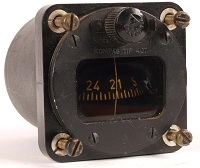
TYPE A
Technical Data
Dimensions ( Ø x height): x mm
Label:
 |

|
|

|
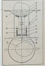
Type 03
Technical Data
Dimensions ( Ø x height): 82 x 106mm
Link to view of main parts

|
- P -

Albert PATIN was an engineer and
industrialist who lived in
Germany in the 1930's and during WWII. He filed among others a
Patent (
no. 853.724) for a
remote indicating (or
distant reading, DR) compass (
compare
to BISSON's patent for a ship compass). This system was
installed in the German
transport aircraft type
Junkers
52. He created in 1938 his own company
Albert
Patin Werkstätten für
Fernsteuerungstechnik GmbH*
located in a village called Mittelsteine (renamed Ścinawka
Średnia in 1947)
at the
Slovakian-Polish border where he developed and manufactured various
devices for the German Airforce
Luftwaffe (French
and German patents)
. The
company's condidential three-letter code was
gzy. A. J. Hughes
writes in his History of Air Navigation (1946) :
The Patin compass [see pic. at
r.] is a repeater compass that has proved to be one of the most
important compasses in this war. After
WWII, U.S. special services brought A. Patin to the USA so
that he worked for the U.S. Airforce together with many other German
technicians and scientists (link to
excerpt
of W. Samuel's book
American
Raiders) although he participated in the Nazi Germany's
war industry (link to
excerpt
of Linda Hunt's book
Secret
Agenda).
* Translation:
A. P. Remote Control Engineering Co. Ltd, in
red on the paper:Flight
Safety
SEE ALSO NAUTICAL COMPASSES
Source: German Archives, Col. Gaujour (s. below),
Wikipedia, Secret Agenda (L.
Hunt, 1991),
American Raiders (Wolfgang Samuel,
2004).
|

(Pictures
by courtesy of deutscheluftwaffe.de)
|
Descr. in col. Gaujour's compensation
instructions (1946). A
picture of the system called Patin
Repeater Compass (invented in 1933?) was also published in
the book History
of Air Navigation by A. J. Hughes (1946). |
Technical Data
Original Luftwaffe doct.
 |

Label on 1st series instrument |
|


Three versions of the pilot slave compass
KT / f8 |
Patent no. 853.724
Fig. 2
 |
Note: This entry is about
aeronautical compasses. For ships compass patterns please got to
Nautical Compasses / DENT & Co.
The British Ministry of Defence (MoD) defines its requirements for
supply of instruments, weapons, equipment, by the issue of patterns.
Any supplier may manufacture and offer such items for sale,
but those items will be examined and certified as type-approved, i.e.
they comply with the official pattern. A pattern number is
purely a mark of compliance to a standard set out by the MoD.
In the following examples, the compass
Pattern 200 is a
mix of the typical aircraft compass featuring a horizontal card
(installed in the lower part of the instrument panel and to be read
from above) and a prism for observation at eyes' height. The
Pattern
200 was the first compass to be officially designated an
aeroplane compass. It was designed and patented by Captain
Creagh-Osborne (patent no. 1148/15, see also marching and wrist
compasses). This design was continuously used but without the prism
until at least the end of WWII on the Air Ministry compasses.
The instrument
Pattern
223 is the only British a/c compass that we know
of featuring quadrantal side spheres for correction of
deviation (compare with the French VION compasses). Go to the
HUGHES chapter for more
patterns (especially the
Centesimal
design).
The compasses
Pattern
255, 259 and 261 are displayed in the chapter
Creagh-Osborne above.
(See also Verner's pattern and Nautical Compasses / DENT).

Pattern 250, 251, 252
For more
information about this series go to Creagh
Osborne
|

Pattern 253 D.B. (Dead
Beat) & A.C. (Centesimal
Aperiodic Compass),
Pattern 254 (compare to
the Air Ministry O.6 Landing Compass,
see also HUGHES)
|
Pattern 255, 256, 257, 258, 259.
Pics above and at
left: Air Pub 802
|

Pattern 261 micrometric (identical to the marching model)
Pattern 5/17: s. Creagh Osborne
Pattern 5/27: small Pattern 253
Pattern 6/18 and R.A.F. MARK II:
see chapter Air Ministry (A.M.)
|
PDK / ПДК in Russian
PDK is the abbreviation of
the Russian words Потенциометрический
дистанционный компас (ПДК) i.e. Distant Potentiometer Compass). These
instruments
were made by a Russian manufacturer. No other data momentarily
available. Your help is needed. Two models are known: PDK-3
and PDK-45. These are master compasses. They feature only a
small compass inside a round window and deliver a signal for
indicators in the cockpit (see
PDK-49 below) and elsewhere in the aircraft called repeaters.

|
 (Pictures
courtesy eBay seller Bokluci)
(Pictures
courtesy eBay seller Bokluci)
|
PDK-49
Technical Data
- Dim.: 100 x 80 mm.
- Inscription on label:
УКАЗАТЕЛЬ РДК-49 = Indicator PDK-49
|
Nautical instrument used onboard of ships. Go to
BEARING COMPASS.
Dr. James PENTZ published in 1919 in several reviews and
newspapers a description of a compass that would also tell a
pilot of an aircraft in the clouds where up and down is. This system
was also studied by a U.S. government agency (Rep. no. 128 / 1923).
Maurice Percheron was a French aircraft
engineer. He wrote a manual about the use of the map and the compass in
aircraft (1917).
The drawing of the compass doesn't seem to represent a specific compass
model. Read his
biography on the website of the
French editor Denoël.

|
Fig. 4 - Setting the course for a flight from Evreux to
Beauvais (50° N-E) taking the declination into account (NM = magn.
North) |

Fig. 9 - Taking side wind drift into account
(Click on images for enlarged views)
|
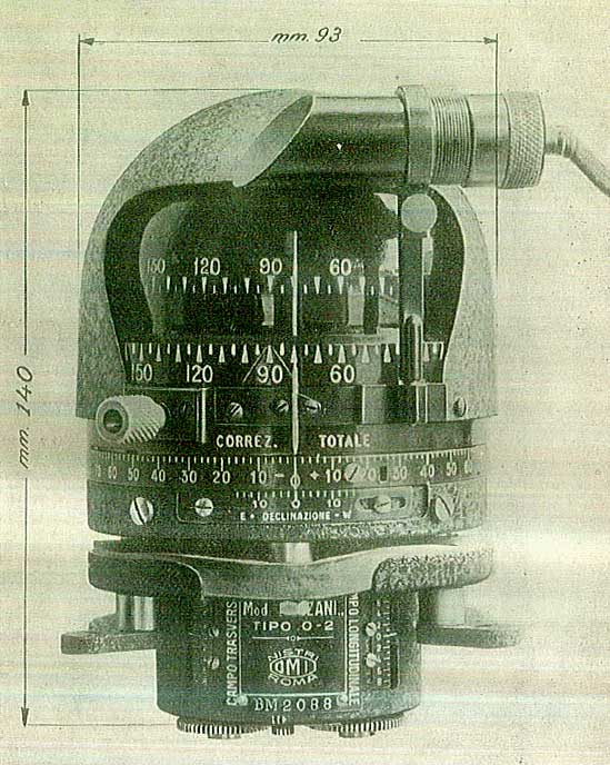
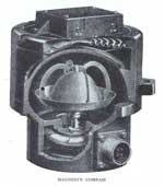
PEZZANI Tipo
0-2
The Italian manufacturer Ottica Meccanica
Italiana (OMI), founded in Rome in 1926 by Umberto Nistri (1895 - 1962)
and taken over by AGUSTA in 1980), produced from the
early 1930the end of WWII a compass called PEZZANI
Tipo 0-2 (
for
more details go to historicacollectibles - featuring
a button for automated translation).

Picture courtesy historicacollectibles.com
(see
more pics on this website)
|
|

Photo at left and drawing above: handbook
(1931/1936)
(Click on images
for enlarged views)
|
Technical Data
Dim.: see fig. at l.
Weight : 2 1/2 lbs/1.250 kg |
Pfadfinder für
Aviatik GmbH
see PLATH below.

PINEDO
In 1925 the Italian marchese di Pinedo flew from Rome to Australia,
then to Tokyo and back to Rome. He had designed his own
version of an aperiodic observer's compass type
S.O.2 that equipped his
Savoia-Marchetti seaplane (source: H. Hughes,
History of Air Navigation
1946, p. 49 - pictures at right:
History
of Air Navigation and
Instruments
for Aerial Navigation, 1930s - enlarged view).
PIONEER
The U.S. manufacturer PIONEER Instrument Company was created
in 1919 by Morris Maxey Titterington and was acquired by and
became a Division of
BENDIX
Aviation Corporation, New Jersey (N.Y.) in 1928. For more information
go to our BENDIX entry and check also "Rockwell Collins" in Wikipedia.
The inventors
Adolf URFER
and
Ch. H. COLVIN
(among others) filed patents for compasses when working with Pioneer
& Bendix. Pioneer invented the MAGSYN Compass and also produced
the
Earth
Inductor Compass utilized by Lindbergh on his transatlantic
flight in 1927 (falsely called there Earth INDICATOR compass!). More
details
HERE. See also SALMOIRAGHI below.

Picture courtesy R. Pavan
(Click on the image for enlarged view) |

View of the compass in instruments panels
|
Technical
Data
The design's patent was filed by J.
P. WARBURG in 1919.

|
 C. PLATH
 was
a German manufacturer (more information
in Nautical Compasses) who took over
Pfadfinder für Aviatik
after WWI and built many aeronautical compasses.
The first models featured a counter-clockwise 360 degrees scale on the
bowl's rim
and some were apparently only half-gimballed probably to be mounted in
Zeppelin balloons were lateral bank angles are negligeable.
Descr. and
user instr. in the book
Der Flugzeugkompass by captn. Fritz
Gansberg, 1917
(copy
available).
Pic.
at r. courtesy McMillan
Pfadfinder
für Aviatik (link
to ads 1915 & 1917) was a German maker
located in Berlin-Johannisthal who built a compass of the same
name during WWI. It was probably bought (after the war?) by C. PLATH
who built several compass types of the same name (see pics below).
The museum
Musée
du
Léman in Nyon, Switzerland, possesses a
Pfadfinder für Aviatik
compass which is said to have been installed on the steamship
Dauphin
(1882-1916). Its card is printed on a float and features cardinal
points in German, counter-clockwise.

Pictures courtesy Jürgen Plesse
(Click on the images for enlarged views) |

Inscriptions on both sides of the NORTH mark:
Pfadfinder* Armee-Kompass III
(* pathfinder)
On the opposite side of the disk:
C. PLATH - HAMBURG
|
Technical
Data
- Dim. (dia. x height) : 120 x 90mm.
- S/N: 17160
- Divisions: 360° clockwise every 10° both on the disk and the chapter
ring of the bearing setting hand
- Lighting device: side lamp

|
The Pfadfinder compass in Der Flugzeugkompass

|
Compass types Z9 and Z10
Rose Ø: 95 mm / 40 mm

(Zum
Vergrößern, Bilder anklicken) |
Suspended compass Z4h and
compass with projected rose image PH 10
Z4h weight: 470 g
 |
 Functional descr.
of the PH 10 compass
Functional descr.
of the PH 10 compass
See pictures of an instrument on the site deutscheluftwaffe.de
(The
enlarged image shows the original German text. Read the translation
below)
|
The images at left were
published in the Luftwaffe handbook
Die
Luftfahrt-Navigation
(cptn Sönnichsen,
1940)
 Rose and glass in cylinder Rose and glass in cylinder
|
See PLATH, type PH 10 above. Translation of the beginning of the
description in German: "
The
compass with
projected rose image is
used both as a steering
compass and as an
additional device for various functions of aircraft radio direction
finders. The magnetic system of this compass consists of a
rose that has a diameter of 17 mm (see pic. above) and a total weight
of just under 0.4
g. Using optics, the rose image is projected onto a screen at a
magnification of eight times. Since
with the reduction in size of the magnets the magnetic moment only
decreases in direct proportion, while the weight simultaneously
decreases to the third power, the projection compass is left with a
disproportionately large magnetic moment, while the decrease in weight
causes the friction on the pivot to become almost zero."
See the full
original German text HERE.
Compass made by the Polish optics
maker P.Z.O. created in 1921 in Warsaw and sold in 1996.
Successor of
Fabryka
Aparatów Optycznych i Precyzyjnych H. (Henryk) Kolberg (Optics
and Precision Instruments H. Kolberg). This compass is called
Z-6 and described as
having been built by
H.
KOLBERG i. Ska (i.e. & Co.) on the Polish
web sites like the forum on Polish Aviation
Lotniczapolska. The instrument's
label indicates
ZÜRN
SYSTEM, so that the inventor should be an engineer called
ZÜRN about whom no information is available. The only other information
available about this compass are to be found in the French
book
L'aéronautique
en Pologne (1935, p. 117/119). Source: the Museum of
Polands Aeronautics' (
Muzeum Lotnictwa Polskiego) online
library (see note and watermark on pictures below).

Pic. court. W. WOZNIAK |

|

Pictures
courtesy Muzeum Lotnictwa Polskiego
(Click on the images for enlarged
views) |
Technical
Data
Dim.: unknown; weight: 3 lb 12 oz / 1.7 kg
Installled on Bomber aircraft Pzl 37
NOTE:
The Museum of Polands' Aeronautics offers an online library but the
access is only possible on the Polish version, the English version is
not implemented: first click on Zbiory in the pull-down menue, then on
Biblioteka
i Digitalizacja
and then on the red words Digitalizacja
zasobów ikonograficznych i archiwalnych MLP. The list comprises numerous
works in several European Languages. |
- R -
Radiation hazard, radioactivity
The self luminescent paint used for markings between the years 1915 and
1950 contained Radium. Click
HERE for more details.
See:
BENDIX (USA),
UGR-4 (Soviet-Union)

R.A.E. / R.A.F.
- Royal Aircraft Establishment / Factory
The designation of the first compasses specially designed for
aircraft is somehow confusing (Air Compass, Aerocompass,
R.A.E. / R.A.F etc.). Most of them are described here in the
AIR MINISTRY chapter but some
will be found in the chapter dedicated to one of their inventor Cptn
CREAGH-OSBORNE. The compass designated R.A.F. was developed
by the ROYAL AIRCRAFT FACTORY in Farnborough, not to be confused
with the
Royal
Air Force (R.A.F.) which resulted from the
merging of the
Royal
Flying Corps (air arm of the British
Army) and the
Royal
Naval Air Service (RNAS) in 1918. The abbreviation RAE /
RAF refers hier to the
Royal
Aircraft Establishment / Factory founded in 1910
in Farnborough which participated in the specification of
navigation compasses and bombing sights (s. a. ANDREWS
inverted compass).
Picture
at right: The R.A.F. pilot's compass Mk II and the Air Compass Mark II
(excerpt of Report
no. 128)
Repeater Compasses
As its name implies,
the remote indicator of this type of instrument comprises a full 360°
repeater dial read against a lubber-line, or a fixed 360° dial with a
revolvable pointer. The repeater is usually fitted with an adjustable
grid to prominently denote the course set to be steered'
(source: A. J. Hughes,
History
of Air Navigation, p. 102-103). Example:
PATIN. Check also the table showing
the separate
development of Tele- and Repeater compasses
(source: ibid. p. 106).
ROSENFELD
This compass was designed by Henri Rosenfeld, 38,
rue de Notre-Dame-de-Nazareth
.
In the (luxurious) flyer, he pretends that fluid-filled compasses were
not as good as dry-capsule compasses...
 |
 |
 |
Technical
Data
- Dimensions : ?
- Weight : ?
- Production period: probably WWI
Original flyers
available
|
- S -

Angelo Salmoiraghi was an Italian engineer (1848-1939, see
his photograph in Wikipedia in Italian language) who joined in 1870
the manufacturer FILOTECNICA located in Milano and became its
head and owner later. A compass called type
ns 1200 was
described in the French review
L'Aérophile in
Aug.1936. Two models were offered:
Atlantico
(rose window breadth: 94 mm) and
Mediterraneo
for light aircraft.
(For original version click on
image at r.)
Salmoiraghi is also famous for his driftmeter (see DALOZ) and for an
adapted version of a
PIONEER compass
(see below) signed FILOTECNICA
.

Pictures
courtesy R. Pavan |


Instrument with lamp - At right: click for full text of advert. |
Technical
Data
- see pic below

|
Michael Sendtner A.G., Fabrik für
Präzisions-Instrumente, München, Schillerstraße 22 (Munich, Germany).
The company founded in 1879 (closed in 1930?) built precision
instruments (telescopes etc.). This compass principle is
similar to the models issued to the German Imperial Navy (
Kaiserliche Marine),
namely C. Plath's
Pfadfinder
and Ludolph's.

Pictures
courtesy bonic_de2014 |
 |
Technical
Data
- Ø bowl: 115 mm, height: 60 mm
- Ø Compass card: 85 mm
- Weight: 4.8 lbs
- Production period: WWI
Description (in the NASA Technical
Report No. 128, 1923)
|
 |

Maxime Louis Jean
Clément SERPEILLLE
was granted a patent (no. 423,468 on 19 Apr. 1910) for a drift
correction device called Map Compass for Aircraft (
Boussole-carte destinée à être
employée plus spécialement en
aéroplane, dirigeable et autres machines volantes). It was
described in
L'Aérophile,
issue 15/1/1912 (copy available). This system
resembles Daloz' design. It was built by HUE (HUET
?), constructeur
d'instruments de précision, 63, rue des Archives, Paris. (at r. : Fig.
2)
 Sestrel
is the trademark brand of
Henry
Browne & Son who were important British compass
makers. This company was sold to John Lilley & Gillie
Ltd and SIRS Navigation (both in UK) in 1993 (read more in
the section Nautical Compasses).
The
version Mk II of this instrument was described in the aeronautics
review FLIGHT in Feb. 1933 (compare to the A.M. / Air Ministry
compasses) where it is designated an
a-trochilic
compass, another name for
aperiodic.
Click
on the image at right for fulll description.
 |
 |
AIRSHIP
COMPASS
Technical Data
- Dim. (H x Ø): 160 x 115mm
- Weight: 2.35 kgs
- Manufacture date: WWI
Pictures
courtesy G. Rooney |
|
 |
 |
 |
Technical
Data
- Dim. (H x Ø): 100 x 200mm
- Weight: c. 5 kgs
- Production year: early 1920s
Pictures courtesy videmaison2000
|
The Eugene M. Sherman Company of Seattle designed and manufactured
nautical navigational aides, notably the line of Dirigo gimballed
compasses. A.S.S.C. (see label below) was the Aviation
Section Signal Corps, which was the aerial warfare service of the US
Army from 1914-1918. R.A.F. was likely the Royal Aircraft Factory (aka
the Royal Aircraft Establishment) and not the Royal Air Force since the
latter didn't come into existence until 1918. R.A.F. was a British
aeroplane
maker which manufactured 3 aircraft used during WWI by
the American Expeditionary Force (A.E.F.): B.E.2
Reconnaissance aircraft, F.E.2 Fighter/Bomber, and the better known
S.E.5 Fighter.
(Source: AeroAntique.com).

Pilots Compass
Pictures by courtesy of AeroAntique.com |

|
Technical
Data
- Dim. (H x Ø): 3 x 6 " / 77 x 152 mm
The markings on the compass card have long since faded
Label:
A.S.S.C. U.S. ARMY
R.A.F. Pilots Compass
EUGENE M. SHERMAN
SEATTLE WASH. USA
|
The
Sherrill Research
Corporation was founded in 1938 in
Peru,
Indiana, and later headquartered in Mexico, Indiana. It made Sherrill
(and later Air Way) brand compasses for decades for automotive,
marine, aviation and military use. We display here the AEG models and a
special version called M6 designed for the M6 battle tank and other
WWII land vehicles. Read a comprehensive description
HERE.


The models AEG and AEG-1 look the same
Picture at right courtesy friebe-aero |

Model M-6
Fig. excerpt of the
Instruction
Manual
(link to a view of the tank) |
Technical
Data
- Dim.: 200 x 160 x 150 mm
- Ordnance drawings no. C121174 and 7067878


Ads for models AEG and M-6 published in Flying Magazine,
Aug. and Dec. 1944
|
Siemens & Halske was the name of a German company established
in 1847 by Werner von Siemens and Johann Georg Halske called
Telegraphen-Bauanstalt von Siemens & Halske and located in
Berlin.
1 - Siemens developed shortly after WWI an electrical
tele-compass.
2 - Auto pilot with a tele-compass for rudder command
3 - Gyro-magnetic compass (
Kurskreisel)
Lku4, Siemens-Halske, built 1943-1945. This equipment was installed in
the instrument panel of the German Junkers aircraft Ju 52 and Ju 88.
The center picture shows a JU 88 cockpit. The Lku4 appears (in red) at
the top in the middle of the instrument panel.
Excerpt from the original notice "D.(Luft)T.5404", issued January 1943:
"The upper scale is the course setting rose. The desired course is set
by means of a motor activated by a flux valve. The lower scale shows
the actual course indicated by the inertial navigation system (gyro)."
|
(Click on image for enlarged
view)
|
1 - (At left) Tele-compass
with electrical data transfer.

Compass for auto pilot (s. drwg. at right)
|
 2 - Tele-compass as a signal
source for the rudder command (1935) 2 - Tele-compass as a signal
source for the rudder command (1935)
Image at right: click for full view of functional drawing |
(Click
on picture for detailled view of front and rear side)
|
Flight deck and instrument panel of the Junkers Ju 88. The
Lku (in red) was located at the top, center.
(Click on picture for an enlarged view) |
 Technical Data Technical Data
(original in German
dated March 1940)
- Dimensions: 160 x 130 x 120mm
- Weight: 2.6 kg.
|
Model name of a compass sold by Air Transport Equipment Inc.
(ATECO) New York. USA. Probably identical to the type F made by
Consolidated Instruments.
|
|
|
Technical Data
Dim.: 7" high x 4.5" wide.
Overall depth: 3"
(Pic. courtesy cturtles1958
- Click on the images for enlarged views)
|

Company founded in 1851 by instrument maker Samuel
SMITH, watchmaker to the Admiralty (
read
more in Wikipedia). Aircraft
business started with the outbreak of WWI. Henry Hughes became a
subsidiary of SMITH & SON in 1935 but the
HUSUN compasses already
appear in
ads published in FLIGHT
in 1929 under SMITH's logo together with one
P4
model called HUSON
(the abbrev. MA between the wings stands for
Maker to the Admiralty).
The only other occurrence of this compass designation is found in
Aircraft and Flying
by Monk and Winter, Gresham Publishing Company, London, 1934. The short
technical description is that of the "dead beat" or "
aperiodic" principle.
NOTE: We cannot rule out that the designation HUSON is a typo or a
momentarily used abbreviation for HUghes & SON.
See also SPERRY GYROSCOPE in Wikipedia. An early large
compass (76mm Ø card) called
Navy
standard compass no. I (pic at right) was
carried in large flying boats and bombers. It is described in the
Report
no. 128. For unknown reasons, it is also described in FLIGHT
(date ???) as a
Mk XVI! A smaller Type II (50mm Ø
card) was used on the smaller airplanes. Another one was an adapted
Creagh-Osborne design called
Air
compass Mark II. As early as in 1915, Sperry had developed an
instrument called
drift indicator.
The compass used was the first
KELVIN
aero-compass.
(Click on the image for an
enlarged view) |
Technical Data
- Dimensions: 70 x 60 x 60 mm
- Weight: 8 ozs./240 gr
- Manufacturer: AIRPATH
- Type: C2300
- Date stamp: APR 82.
The deviation can be rectified by turning the screws concealed
behind the plate at the lower front part:
- the left hand screw is for the north-south axis
and
- the right one for the east-west axis. |

Former manufacturer of compasses located in Boston,
Massachusetts,
created by Gustave A. Salzgeber who patented in 1931 a compass design
(no. 1,799,648, copy avlbl.) also produced by
Consolidated
Instruments (source
Milton Historical Soc.).
Click on the image at
r. for a full-page view of the patent figs.
Telltale (overhead) compasse produced by this Swiss
manufacturer (read more details about the company in the dept. SURVEY
COMPASSES). Read below its description in
Report
no. 128.
|
|
Technical Data
(Click
on the images for enlarged views)
|
 
Picture
courtesy histoirémilitaria |
- T -

Apparently some tests were conducted during WWI with compasses fitted
in battle tanks (see
SHERRILL
and
VION).
Captain F.
Creagh-Osborne
R.N. wrote a
booklet (
The Magnetic
Compass on Land, 15 p., 1915) for the
armoured
car section of the Naval Air Service (
link to short description, p. 14)
but he mainly describes therein
two other
instruments (p. 7 & 8), a wrist compass (see
Chetwynd/Kelvin)
and a marching compass featuring a
lense-shaped lid - designed by himself.
Picture courtesy S. Wiggins
NOTES: We received a message sent by a former Lt Col of the Royal Tank
Regiment about a document kept in The National Archives (TNA,
WO 194 54 - Tanks and Ancillary Vehicles 1915 - 1918 - Notes-
Mechanical
Warfare Department, Inspection Department Royal Arsenal dated Jan 1925
Mark V Sheet 1) telling us "
that
the Mark V was the last British heavy tank to be used in WW1 and had an
extensive number of modifications / improvements compared to the early
Mark I to IV. The reference does mention when a specification was
planned but not implemented and the compass has no such caveat by it.
"
Another contributor wrote:
"All
I know about tank compasses, is that they never worked reliably. Every
time you changed the direction of the gun barrel or its elevation, the
compass card flew all over the place. The Americans tried them. Bendix
made various models (see type 1829), but they just didn't work. In
desert conditions they used sun compasses. Later, in the 1960s and
1970s they started using gyro compasses. Nowadays they use GPS."
The French system called T.A. 103 builds the transition from
the pure compass-based navigation to a compound system in which a
compass delivers a signal to several devices to form a magnetic
gyroscopic navigation instrument, i.e. a compass gyro. The letters T
and A are the initials of its inventor
J. C. Thédenat (see
below) and of the company that built it,
ALKAN. It was at the
base of the development of the system called D.R.C. (Distant Reading
Compass).
Description (
only in French available)
in col.
Gaujour's
book, 1946. Link to pic.:
Le
club des collectionneurs / Collection Willys69.
This type of instrument was invented after WWI. Several technical
solutions were developed first by
C.
Bamberg (optical device),
Askania
(pneumatic d.) and
Siemens
(electrical d.). In 1932
Holmes
and Hughes added another design made by Smith's Aircraft Instruments
(read
descr. in Flight).
It was a primitive remote indicating compass not to be confused with
the improved system called
repeater
compass (example:
PATIN).
The indicator of a tele-compass is not a conventional compass dial but
merely a centre zero dial with a swinger pointer (galvanometer) which
plainly shows when the plane is headed right on its set course or is
deviating therefrom to the right or left. Check also the table showing
the separate
development of Tele- and Repeater compasses
(source: A. J. Hughes,
History
of Air Navigation, p. 106). Compare with BAMBERG's
photo-electrical system and with MOREL typ CR12 Mengden.
Jean
Camille Thédenat (1901-1935) was a French Navy officer and a
pilot. He invented an early compass gyro called Appareil Directeur
T.A. 103. He filed a
patent
no. 793.300 * (published on Jan. 21, 1936):
Perfectionnements aux
installations permettant à bord des engins de navigation, notamment à
bord des aéronefs, de déterminer, de faire prendre à ces engins et de
contrôler le cap convenable pour la navigation et pour le jet sur un
point déterminé de projectiles ou charges quelconques, ainsi que pour
d'autres fins.
* Note: on fig. 1, the compass is referenced by the letter C.
Profile: see Marching Compasses. This compass is displayed in an
instruments panel shown in an
advertisement for the company
Korect
Depth
Gauge.
Model T.LK18
Production date unknown, probably before WWII
 |

Name T.LK18
and S-zero-Y line
Pictures by courtesy of M.
Doveton
Click on images for enlarged views
|
Technical Data
Dimensions: 100 x 80 x 80 mm
The cardinals (N, W, S, E) and
half-cardinals (triangles) which were printed
with radium-compound paint have turned black with the time.
NOTE:
We cannot guarantee for sure that this instrument was produced by
TELEOPTIK.
This assumption results from the study of the inscriptions
left and right of the north marking. The various letters can be
interpretated as the maker's name and designation of the instrument: T.LK
would thus stand for Teleoptik
and Letač
Kompas, i.e. Pilot Compass if we are right in assuming that
it is written in a Slav language in latin letters
like Polnish, Czech or
Kroatian. Since we only know of a single maker whose name begins with
the letter T in these countries namely Teleoptik in former
Yugoslavia, we consider that the language must be Kroatian. On the
opposite side of N we see a line with three letters which we
read as follows:
___S__0 (zero)__Y___
In all Slav languages, the cardinal point North is
called Sever (abbreviated S) and South "Yug" (like in
Yugoslavia, (see menue Miscell. / Cardinal points- table -
Serbocroatian). This could represent a symbolic view of a correction of
the deviation. Since this instrument features a connector
(link to picture)
and there are no screws to perform such a correction we consider that
this compass was slaved and didn't need any correction of deviation. Thanks for helping if you have
1st hand information.
|
Pictures Compassipedia
Click
on images for enlarged views
|

|
Model (Tip = Type) 407:
Production date unknown, probably after WWII
Logo of Teleoptik (T in a triangle)
Technical Data
Dim.: ... mm
Designation in Kroatian language: Pilot Compass
There is another model designated TIP 443 but have no picture of it. |

TILLANDER
SILVA's head Gunnar Tillander invented in 1944 an aircraft compass.
Pic. at right: Figs of U.S. patent no. 2,359,691.
TITTERINGTON
Morris Maxey Titterington was a
US inventor. He founded PIONEER and invented the
earth
induction compass (see also Lindbergh).
- U -
UGR-4 (УГР-4 in
cyrillic letters)
Russian-made (USSR) radio compass. Unknown
manufacturer
Pictures courtesy K. Pätzold
Marking on dial:
KURS - RP |
The label reads:
UGR-4Uk SERIA 3
(Click for enlarged view)
|
Technical Data
- Diameter: ? mm
- Weight : ? kg

|
Adolf URFER was an inventor who filed at least two
patents implemented in compasses built by
Pioneer
/ Bendix, the #
1.873.684
(in 1932) and
1.939.374 (in 1933).
Former French company (for more information click
HERE.
Visit also the sections nautical and survey compasses).
Fig.
at r.: advertisement published in L'Aéronautique (Paris, 1923)
- Source: gallica.bnf.fr
The
compensation
procedures for some VION compass types are explained in
Capitaine Gaujour's book (
copies available).
See also our entry about the FUNCTIONAL TESTING DEVICE
(click on link for immediate access)
Auguste Henri Eugène VION filed several patents between the two World
Wars. They describe precisely the development of the main instruments
shown below. Some were translated into English (UK and US issues) and
one into German. The successor company
Société
d'Exploitation des Etablissements VION also filed 2
patents in 1966.
French Patents and US or
GB issues if available (copies
available)
- 558.994 - Perfectionnements aux compas à liquide - gobe-bulles et
éclairage en-dessus (sept. 1923)
- 564.946 - Dispositif pour la compensation des déviations des roses de
compas (janv. 1924); GB:
Compass
for Navigation Purposes, 214.209; USA: 1.596.639
- 639.734 - Compas de pilote avec dispositifs pour sa transformation en
compas de relèvement (janv. 1928); USA: Compass, 1.694.194
- xxx.xxx - Compas pour avions (ou aéronefs -
titre supposé, 18 juin 1927 - voir détails dans le tableau); GB:
Improvements in or relating to
Mariners' Compasses, 292.489 (15 nov. 1928); USA:
Magnetic Compass for Aviation,
Navigation and other Purposes, 1.962.312;
Germany:
Kompass,
insbes. für Flugzeuge, 566.628 (1928 / 1932)
- 640.901 - Dispositif pour la compensation de la déviation
supplémentaire des roses de compas (juil. 1928)
- 670.915 - Dispositif pour l'observation et la rectification des
orientations de marche, en navigation aérienne ou maritime (déc. 1929);
GB:
Improvements in
Electro-magnetic Apparatus for the Observation and Correction of Travel
of Aerial and Marine Craft, 314.786
- 749.267 - Perfectionnements aux compas pour pilotes (1932) - see
table below
- 794.813 - Compas de planches de bord, pour navigation
aérienne ou autres applications (1934) - see table below
- 798.902 - Compas à rose cylindrique dite "verticale" (1935) - see
table below
 Wing compass V.P.S. 28 Wing compass V.P.S. 28
(patent no. DE*
566.628, U.S. pat. no. 1,962,312, 1928). It was attached to the wing
above and in front of the pilot's head. The angle values could be read
via a prism.
* DE stands for DEUTSCH = German,
We didn't find the French original patent no.
(Click on images for enlarged
views) |

Click on image
for view on aircraft |

German issue, page 1:
This invention was patented on June 19, 1928 but published as late as
on December 8, 1932 only! |
French
pat. no. 749,267 (1932)
|
No.
794,813 (1934)
|
No.
798,802 (1935)
|
No.
1,501,923 (1966)
Spherical case
|
No.
1,505,506 (1966)
Topic: friction of the pivot
|
VION
catalogues/manuals for compasses with vertical (pic. at left) and with
horizontal (right) rose:

Enlarged view: Text and Figs.
(Photocopies
available) |

In a manual for
compasses
with vertical rose of winds (1930's) we find a list of
the VION compasses then available:
- Type V.31 (dia. 60mm) for fighters and T.31 for tourism
aircraft,
- Type Q.S.C.V.29 (dia. 85mm) for reconnaissance aircraft, bombers and
also for medium-size airmail and commercial aircraft
- Type G.N.R.V.30 (dia. 120mm) for large-size commercial and freight
aircraft and heavy bombers.
Picture
at right: Cockpit of a Latécoère 631 with the compass types V.A.82 and
150 (behind the steering horns)
Courtesy Collection ville de Biscarrosse-Musée de
l'Hydraviation-Origine Moine)

Compasses with Horizontal
rose of winds:
- Orientation : Q.S.C. 25 Pilote (Navigation)
- Navigation : Q.S.C. 27 Pilote et Relèvement (pilot and bearing
compass)
- Grande Navigation et Grand Raid : Q.S.C. 27 Pilote et Relèvement.
Two other
special
compasses are also described in the book
Traité
pratique de navigation aérienne (Duval & Hébrard,
1935) :
- type P.B. 50 (PB = planche de bord = instrument panel, see
below) and
- type
H.
32 for aerial photography
Picture
at right: Cockpit of a Potez 54 with the compass type GNRV 30 in North
Africa in 1942 on a reconnaissance base
Courtesy U.S. Army archives
Land vehicles
These two instruments (Type 14 and 143) were installed in UV's driven
by French geologists of the French Nuclear Energy Authority
(CEA) in the 70's in Africa (Niger). Information and pictures
communicated by P. C. Guiollard, Ph.D. in History of Science and
Techniques and collector of mine compasses.
Type 143 featured an integrated red-light illumination.
|
Type 14
Scale seen from below
Pics courtesy
P.C. Guiollard |
Type
14

The compensation mechanism (on top) |
Type 142 - 143
|
Technical
data - Type 142 - 143
Dia. (incl. screws): approx. 2 in. / 50 mm
Height (incl. lighting tube): 2 2/3
in. / 65 mm
Built: 1970's
Integrated lighting device in tube below
(link to pic. dismantled)
Access to compensating screws via slide top.

 |
- W -
WARBURG
J. P. WARBURG was a U.S. engineer residing in Washington D.C.
who patented a magnetic compass in 1919 (no. 1,474,394).
This design was re-used by HUGHES & Son and PIONEER.
The abbreviation W.D. stands for WAR DEPARTMENT. We don't know
on which vehicles and during which period this instr. was
used. Thank you for helping us.
Pictures courtesy
Bernie |
|
 |
Technical
Data
Dia.: 80 mm
Period: Probably WWII
|
This company
published
an ad in the booklet The Magnetic Compass in Aircraft by
Captain Creagh-Osborne (1915).
- X -
The following pictures show compasses with no manufacturer's name.
Pictures courtesy
A. Picker |
|
|
Pictures courtesy G. Rooney |

View of the compass card, the 1-2-3-0 cross and the scale for
adjustment of declination |
Technical Data
Dim. (height x dia.): 700 x 500 mm
No external marking
Above the compass card is a cross made of four thin rods bearing each a
mirrored figure with luminous paint: 1, 2, 3 and 0.
They are attached to a central post on top of which is a broad white
arrow (for flight direction?). |
- Z -

ZÜRN was a Polish
engineer who designed aircraft compasses shortly after WWI. The most
famous model is the type Z-6 built by
PZO
(see description and pics in this entry) but a report on the Polish
aircraft industry names more models all beginning with the letter Z,
also listed in the German C. PLATH catalogue.