COMPASSIPEDIA
The Online
Compass Museum


The Online
Compass Museum

 |
 |
|
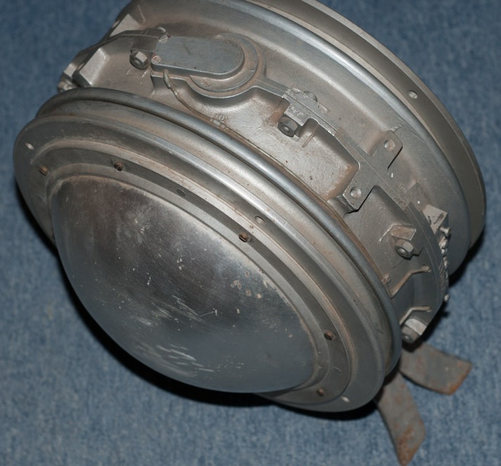
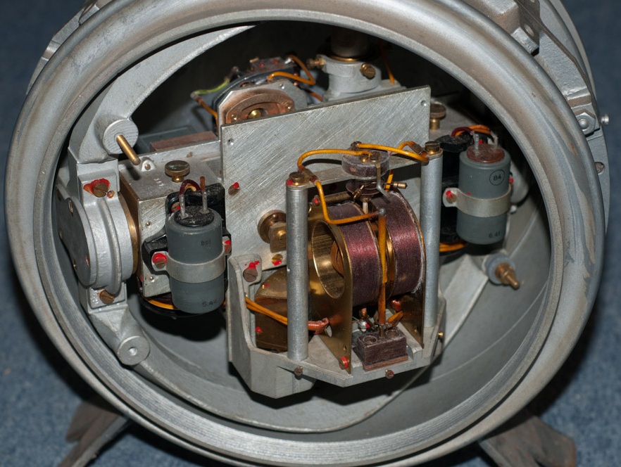
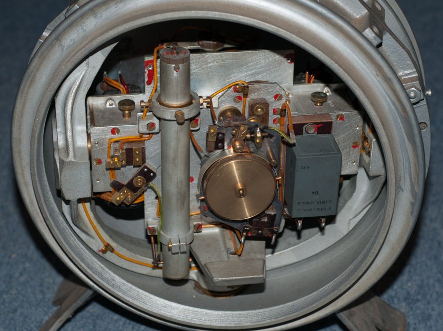
| Modèle marqué T.LK18 Date de fabrication inconnue mais probablement antérieur à la 2e Guerre mondiale.  |
 Photos M. Doveton Cliquer sur les images pour les agrandir |
Fiche technique
Dimensions : diam. ... x ... mm NOTA: Nous ne pouvons pas garantir à 100% que cet instrument a été fabriqué par TELEOPTIK. Ce n'est qu'une supposition échafaudée à partir des inscriptions gravées sur sa face avant de part et d'autre de la lettre N. Supposant que T.LK seraient l'initiale du fabricant et LK la désignation de l'instrument, la seule explication plausible de cette abréviation serait Letač Kompas c'est-à-dire compas pilote en serbocroate. Le seul fabricant dont le nom commence par un T dans un pays de langue slave s'écrivant en lettres latines était Teleoptik dans l'ancienne Yougoslavie. De plus, on distingue à droite du N une ligne et trois lettres (sauf erreur de lecture): ___S__0 (zéro ?)__Y____ dans laquelle le Y représenterait le sud (YOUG comme dans Yougoslavie) et le S (= Sever) le nord comme dans toutes les langues slaves, de part et d'autre d'un zéro (voir menu DIVERS / POINTS CARDINAUX - Serbocroate). Cette gravure symboliserait peut-être la correction de la déviation magnétique. Cependant, comme il n'y a pas de vis servant à effectuer cette opération et vu qu'il y a une traversée pour raccordement électrique située sur le côté (lien vers photo), tout laisse à penser qu'il s'agit d'un instrument asservi à un compas "maître". Ceci sous toute réserve. Si vous possédez des informations sûres, merci de nous aider à corriger cet article. |
 Cliquer sur les images pour les agrandir |
 |
Modèle (Tip = type) 407 : date de fabrication
inconnue
mais sans doute post 2e Guerre mondiale. Fiche technique Dimensions: ... x ... mm Inscription en serbocroate : Il y eut aussi un modèle 443 dont nous n'avons pas de photo. |
| Modell T.LK18 Fertigungsdatum unbekannt, wahrscheinlich vor dem 2. Weltkrieg |
Name T.LK18 und S-Null-Y-Linie Fotos M. Doveton Zum Vergrößern, Bilder anklicken |
Datenblatt
Abmessungen: 100 x 80 x 80 mm Die Himmelsrichtungen (N, W, S, E) und Zwischenrichtungen (Dreiecke), die vermutlich mit radiumhaltiger Farbe ausgeführt waren, sind heute schwarz geworden. Anmerkung: Wir können nicht mit 100%-iger Sicherheit garantieren, dass dieses Instrument von TELEOPTIK gebaut wurde. Diese Vermutung beruht auf der Deutung der Beschriftung links und rechts von der Nord-Markierung, die wir wie folgt verstehen: es handelt sich um eine slawische Sprache, die in lateinischen Buchstaben geschrieben wird (Polnisch, Tschechisch oder Kroatisch). Wir kennen in diesen Ländern jedoch nur einen Hersteller dessen Name mit einem T beginnt, also tippen wir auf Serbokroatisch. Die Buchstaben T.LK stünden demnach jeweils für die Anfangsbuchstaben von Teleoptik und Letač Kompas, d.h Pilotkompass. Auf der gegenüberliegenden Seite vom N ist eine Linie mit drei Buchstaben (vom Zentrum der Windrose betrachtet): ___S__0 (Null)__Y___ Nord heißt in den slawischen Sprachen S (= Sever) und Süden "Yug" (wie in Jugoslawien, s- Menü Verschiedenes / Himmelsrichtungen - Serbokroatish). Es handelt sich unserer Meinung nach um eine symbolhaft dargestellte Einstellungsmöglichkeit der Missweisung. Da es aber keine entsprechenden Stellschrauben gibt, scheint es darauf hinzuweisen, dass die Missweisung automatisch korrigiert wird. Eine seitliche Kabeldurchführung (Link zu Foto) führt zur Annahme, dass es sich hier um ein nachgeführtes Instrument handelt. ALLE INFOS MIT VORBEHALT. Wenn Sie über belastbare Infos verfügen, bitten wir um Ihre Hilfe. |
|
Fotos Compassipedia Zum Vergrößern, Bilder anklicken |
|
Modell (Tip = Typ) 407: Fertigungsdatum unbekannt. Vermutlich nach dem 2. Weltkrieg Logo von Teleoptik (T in einem Dreieck) Datenblatt ... Bezeichnung auf Serbokroatisch: Es gab auch ein Modell 443, von dem wir kein Bild besitzen. |
| Model T.LK18 Production date unknown, probably before WWII |
Name T.LK18 und S-Null-Y-Linie Fotos M. Doveton Click on images for enlarged views |
Technical Data Dimensions: dia. ... x ... mm The cardinals (N, W, S, E) and half-cardinals (triangles) which were printed with radium-compound paint have turned black with the time. NOTE: We cannot guarantee for sure that this instrument was produced by TELEOPTIK. This assumption results from the study of the inscriptions left and right of the north marking. The various letters can be interpretated as the maker's name and designation of the instrument: T.LK would thus stand for Teleoptik and Letač Kompas, i.e. Pilot Compass if we are right in assuming that it is written in a Slav language in latin letters like Polnish, Czech or Kroatian. Since we only know of a single maker whose name begins with the letter T in these countries namely Teleoptik in former Yugoslavia, we consider that the language must be Kroatian. On the opposite side of N we see a line with three letters which we read as follows: ___S__0 (zero)__Y___ In all Slav languages, the cardinal point North is called Sever (abbreviated S) and South "Yug" (like in Yugoslavia, (see menue Miscell. / Cardinal points- table - Serbocroatian). This could represent a symbolic view of a correction of the deviation. Since this instrument features a connector (link to picture) and there are no screws to perform such a correction we consider that this compass was slaved and didn't need any correction of deviation. Thanks for helping if you have 1st hand information. |
|
Fotos Compassipedia Click on images for enlarged views |
|
Model (Tip = Type) 407: Production date unknown, probably after WWII Logo of Teleoptik (T in a triangle) Technical Data Dim.: ... mm Designation in Kroatian language: There is another model designated TIP 443 but have not picture of it. |

Compass
Testing Device  The large disc is rotated by the crank on the right. The small disc is moved by a belt The zero references are the brass pointers to be observed either from above or from the side. (Click on the images for enlarged views) |
Technical Data Dimensions: Ø large/small disc: 277/80 mm Interaxes distance: 250 mm. Ground plate: 255 mm x 500 mm Test procedure / max. values: (see translation at right):  Pictures by courtesy of D. Binon |
 Excerpt
of the Traité de
Navigation Aérienne (p. 8): 
DISC DRAG ERROR After a full revolution effected in 30 sec. - Max. error 12° on horizontal* compass disc Ø 140 mm - Max. error 8° on horizontal compass disc Ø 85-75 and 60 mm - Max. error 7° on vertical* compass disc Ø 60 mm * Examples of VION compasses with horizontal and vertical disc:  |
| Picture posted by 'Guynemer' on the web site "Lagrandeguerre.cultureforum.net" |
 Logo on a bord watch Click on images for enlarged views. |
 Type E 10 Technical Data - Dim.: ... - Weight: ... |
 Picture courtesy ailesyport |
 Picture courtesy ailesyport |
 Pictures: - Left: Ad for model CT (tourism), - Center: Ad for models B (navigator) and C (pilot) - Right: Figure published in Cours élémentaire de compensation et d'emploi by Capitaine Robert Gaujour (1936) giving instructions for compensation (copies available). |
 Picture at
right courtesy
M. Goosey: A P12 compass (click on the image for an enlarged
view).
 -
The P10 was an improved version of the P4 with four cross hairs.
 Pict. Notes on Aero Compasses and their Adjustment (Air Pub. 191, 1918) (For a drawing of a sectional view with the parts list ask the museum's curator via the CONTACT button) (Click on images for enlarged views) |
 Pic. Magnetic Compass in Aircraft (Air Pub. 802, 1920). |
Model
name: R.A.F. Mark II (note: for type Mk III go to HUSUN) Technical Data - Dim.: 9½ x 5½ x 5½ in. (240 x 140 x 140mm) - Weight: 4 lb. 10 oz. (2.3 kg) - Spherical bowl, inside face of inclined glass window also spherical (same radius as bowl), the correction magnets were placed in the "grip" - Maker: Royal A/C Establishment, Farnborough This system was especially developed by Dr. Keith Lukas to overcome the phenomenon called Northerly Turning Error (description in Air Publ. 802 - ask for copies). |
 Comprehensive description available: ask for copies |
 Details: see at right (Click on images for enlarged views) |
Type
6/18 - Aperiodic
Compass - Mark III Technical Data: Inventors: Campbell & Bennett, England from 1918 onwards until superseded by the models described below. - Dim.: height: 1015mm; dia.: 680mm Printed onto crew members training poster (see enlarged view): "AIR MINISTRY / DIRECTORATE OF TECHNICAL DEVELOPMENT / 4-2-26 / AIR DIAGRAM NO 986" Printed below border: "16604 W.977/13657 4/25 R. & L. E.2858" Original photograph courtesy powerhousemuseum post-edited by Jaypee for COMPASSIPEDIA |
| LANDING COMPASS (see definition at right) 1 - HAND-HELD TYPE 06A Stores* Ref. 6A / I.248 * see Miscellaneous/Terminology  2 - GROUND DEVICE (TO BE PLACED ON A TRIPOD)  |
AIR
PUBLICATION 1275 General description and section view 
 (Photocopies of AM compass manuals can be ordered) * A landing compass is used to "swing" the compass installed in the fully equipped aircraft i.e. to write a table with the deviation values (description in the Air Pub. 802, photocopies available). See also BOES below. (Click on the pictures for enlarged views) |
Technical
Data - Diameter: 3.8 in. (95 mm) - Overall length: 9 in. (190 mm) - Weight: 2 lb. 4 oz. (approx. 1 kg) - Serial no.: 38899H The Air Ministry logo (see pic. below) was not engraved on all items. Some featured only the Army's broad arrow ("crow foot").  The compass card's winged North symbol (mirrored view):  |
| TYPE
P. 2 Certain characteristics like the divisions ring and N-S arrow are maybe evolutions compared to the Type P.1.  
(Click on the images for enlarged views) |
The
system was apparently gimballed like ships compasses.
Pictures courtesy G. Rooney The casing without the divisions ring. The aircraft's axis (direction of flight) was represented by means of a long pin located on the casing's side wall opposite to the word AFT. The card's south-north axis was enhanced by means of an arrow featuring a letter S at one end and a letter N in a red triangle at the northern end. The arrowhead features two bird wings with feathers like on the TYPE 06A's card above (click on link for pic). |
Technical
Data
Dimensions - Height: 3 1/8 in. / 80mm - Dia. (top rim): 6 1/2 in. / 165mm - Dia. (base): 5 1/2 in. / 140mm - Dia. of compass disk: 2 3/8 in / 60mm Markings: Type . P. 2 . (with three dots!), AFT, No. 195 D. The card already featured the spider leg-shaped damping wires (see also the exploded view of Type P.6). The card supplier's name in the north symbol (stylized fleur de lys) is HUSUN (click on link for pic). The center letters are masked by the S-N arrow. This is the abbreviated trade name of H. Hughes & Son Ltd. TOP OF PAGE |
| TYPE
P. 3 Front view (compass) 
(Click on the images for enlarged views) |
LH
and RH views:  
Pictures courtesy aspentree123 |
Technical
Data Compass type: vertical type, free rotating sphere Dimensions - Height: 10 in. / 250mm - Dia. of compass window: 2.25 in. / 55mm Weight: 3 lb 11 0z. (1.66 kgs.) Markings Type P3, S/No. 734 H* and a large letter M in white paint; Stores Ref. 6A/O.224 Materials - Compass casing: brass; mouting frame: aluminum, grip: wood |
| Type
P4, P6,
P8 compasses Stores Ref. 6A/O.227, .367 and .726 These compasses had apparently the same shape. Only internal technical details vary. 
 P4
top view and exploded view of P6
(Click
on the
images
for
enlarged views)
|
Side
view:  
A P4 in situ in a Lancaster bomber's cockpit (Cockpit picture by courtesy of www.spitfirespares.com) For a FOOTAGE (part 1of 2) about low-level navigation and compass use click on the image below:  |
Technical
Data P4 - Built in (Lancaster?) bombers - Diameter: 7 1/4 in. (184 mm) - Weight: 5 lb. 14 oz (approx. 2.5 kg) - 4 magnets P6 - Built in ...? - Diameter: 5 3/8 in. (136 mm) - Weight: 2 lb. 4 oz (approx. 1.2 kg) - 2 magnets P8 - Built in Spitfire - Diameter: 5 3/8 in. (136 mm) - Height: 3 in (77 mm) - Weight: ... oz (approx. 0,821 kg) |
|
AIR
PUBLICATION 1275
Click
on the images for
enlarged viewsGeneral description and section view  Photocopies of AM compass manuals can be ordered |
 TOP OF PAGE |
A
compass
in
its transit container |
| Type P7 Stores Ref. 6A/O.430 
 Pictures courtesy G. Rooney (Click on the images for enlarged views) |
AIR
PUBLICATION 1275 General description and section view 
 (Photocopies of AM compass manuals can be ordered) |
Technical
Data Type P7 aircraft course-setting compass with illuminated grid and a mirror in the base to reflect the compass reading. - Diameter: 5 1/2 in. - Height: 8 in. - Weight: 4 lb. 8 oz. (approx. 2.3 kg) |
| Type P.11 "Designed in conjunction with the Admiralty Compass Department and manufactured by Kelvin & Hughes Ltd." Description: slightly smaller than the P10. Type P.12 See List of compasses and picture (blue compass at r.) above |
OVERHAUL AND REPAIR
INSTRUCTIONS (26 pages, 14 figs)  (Available online HERE) |
Fig.
14 - Exploded view |
| Type O2 with azimuth circle Stores Ref. 6A/O.380   Picture at left courtesy Viet-Linh Nguyen (Click on the images for enlarged views) |
AIR
PUBLICATION 1275 General description and section view (Photocopies of AM compass manuals can be ordered)  |
Technical
Data - Dia.: 6 1/4 in. - Weight: 6 lb. 2 oz. (approx. 3 kg) Azimuth circle (stores Ref. 6A/O.411)  Click here for a FOOTAGE about a compass in perfect condition. |
Type SO2 - Stores
Ref. 6A/1078 (Click on the images for enlarged views) |
Side
view of prism
and lamp
fitting |
Technical
Data - Diameter: 16.5 mm - Weight: ? Label 
|
| Bomb
Sight Type D Stores Ref. 6E/O.276  This instrument is primarily designed for use in the course-setting bomb sights Mk VII A, B and C. (Click on the images for enlarged views) |
AIR
PUBLICATION 1275 General description and section view  (Photocopies of AM compass manuals can be ordered) |
Technical
Data - Diameter: 4 in. - Weight: 1lb. 11 oz (approx. 750 gr)  |

| Orterkompass (Observer
/ Navigator compass) Lkf 5b "Franz" Supply no. Fl.23203-1, predecessor model of OK 38 This instrument was also produced by C. Plath and W. Ludolph. Enlarged
view
of the compass card:
click on picture at r. |
 |
Technical data - Dia.: 120 mm - Height: 80 mm (case) + 50 mm (glass dome) - Weight: ca. 750 g (w/o attachment parts) - Techn. Data in the ASKANIA catalogue WWII Material supply document "Flieg" of model OK 38: Fl. 23204. Compare with other versions in this List of German a/c compasses during WWII. Link to picture Instruments panel. |
Slaved
compass assy. |
 Ad. published in 1941
|
Technical Data The assembly comprises the following parts (table: picture of the catalogue)  |
| Kompensier-Peilscheibe
Lp 5 (compensation bearing disc)  Pictures courtesy Jan Hessels |
 |
Technical Data See description in catalogue (click on image bellow left)   |

 |
 Special compass for ballooning as shown in the VION catalogue (c. 1910) Click on picture above for full descr. |
Technical
Data - Diameter: 45 mm - Depth: 12 mm - Weight: 40 gr - Manufacturer: Houlliot - Serial no.: 56 (punched on the side) It was carried in a leather pouch with snap lock and a large round window. Early 20th c. |
 Printing plate for catalogues of Houlliot compass retailers (s. F S & C) |
| Type
700
- Technical
Data Dim. (ext. dia. x ht.): ... x ... mm Photograph of the compass as published in Colonel Gaujour's instructions for the compensation of compasses (1946)  |
 |
Type
120 - Technical
Data Dim.: ... x ... mm Photograph of the compass as published in Colonel Gaujour's instructions for the compensation of compasses (1946), compare to VION's Type 150  |
 |
 |
Type
900 Technical Data - Dim. (ext. dia. x ht.): 135 x 170 mm 
Pictures courtesy pseudo17dom |
 Photograph of the compass in Colonel Gaujour's book on compensation of compasses (1946) |
 |
 Copies of the patents listed on the label are available |
STRAIGHTFLIGHT,
JR. COMPASS -
TYPE 1802-2B Technical data Dia. (dial): 100mm (5 in) Manufactured approx. in 1940 Picture courtesy Ames Swartsfager - Click on the images for enlarged views |
 The upper plate masks a lamp. Pictures courtesy Tony KING (Click for enlarged view) |
 Rear face (connectors) |
AIRCRAFT COMPASS
MARK VIII - TYPE 1822 Technical Data - Breadth: 87mm - Height: 80mm - Weight: 883gr Markings: BU. AERO. U.S. NAVY F.S.S.C. No.: 33-C-800 MFR'S Part No.: 1822-1-B |
 |
Patent
no. 2,188,821 for a
new system
allowing to uniformly illuminate a compass rose (1938). Rylsky
also filed in 1940 a patent (no. 2.227.368) about the internal
electrical illumination. (Click on image at left for view of full page - Photocopy available) |
Excerpt:
"The novel means of the present invention comprise a transparent ring of light-conducting material (40) [...] composed of glass, quartz, "Lucite" or any other suitable material. The light from a lamp (42) may be introduced in the ends (40c) of the ring and conducted thereby around the periphery of the compass. The ring-light is provided with a plurality of light-reflecting surfaces (fig. 2, 40a and 40b) extending around the circumference of the ring, the reflecting area of these surfaces gradually increasing in amount of the distance as the distance from the light source increases." |
 Model D-12 |
 |
The
patent above was
implemented into the
model
D-12
 |
 |
 Cut-away view (Installation instr.) |
PIONEER
VEHICLE COMPASS - TYPE 1829 This compass was used in all sorts of land vehicles incl. tanks. It is said to have also been used in aircraft (Installation Instr. avlbl.) but we lack evidence. Pictures courtesy priv. coll. (Click on images for enlarged views) |
 (Click on the pictures for enlarged views) |
 |
Radio
compass /
Signal indicator I-82-A Signal Corps U. S. Army S/N: 4771 Period: WW2 Technical Data - Diameter: 13 cm - Depth: 9 cm - Weight: 600 gr |
 Picture courtesy worldconflictimages |
 |
The next step was the
integration of the compass into
a complex instrument called Air Position Indicator (ad published
in 1944, Japan is burning...). (s. KEARFOTT, SIEMENS etc.) Picture courtesy worldconflictimages |
 Click on the image for an enlarged view in working position as shown in the original user instruction |
Instrument
used to perform the operation called SWINGING. Read more details HERE. Click here for viewing an ad dated Sept, 1943. |
Technical
Data - Diameter: ? - Depth: ? - Weight: ? - Supply designation and no. : Sight, compass swinging, 42013536 |
 The aperiodical compass designed by Campbell & Bennett |
 Fig: Patent Zum Vergrößern, Bilder anklicken |
Figures
on patent (photocopy available) |
Announcement
published in a patents
review Click on images for full view and text |
Figures
on patent no.
1,679,764 |

Description
and user instructions for Air Compasses (French edition) (Click on the pictures for enlarged views) |
Instrument
panel
compasses
Pattern 255 and 259  Observer's wrist compass Pattern 261  |
The
patent numbers indicated on the compasses (1148/15 and
17736/15) refer to the application documents and the year 1915 (copies available). The compass type described in Pat. no. 17,736 is for the patterns family 255/259. The numbering started in 1913 with pattern 200 and the compasses were issued from 1915 on.  Patent no. 1148 describes several prismatic and liquid dampened compass types displayed in the Marching and the Wrist compasses sections. |
|
Air
Compass Pattern
259
 |
Technical
Data - Dimensions (height x breadth): 152 x 135 mm - Depth (w. lugs): 108 mm - Depth (w/o lugs): 89 mm - Weight: c.1.7 lb. - Divisions: 360 deg. every 10. - Fluid damping  |
|
 Click here for a view of the manufacturer's label of H. HUGHES & Son Ltd. (see below). |
 Pictures courtesy mfc80 |
Technical
Data - Dimensions: 6½ x 5 5⁄8 x 4 in. (165 x 143 x 100 mm) - Weight: 2.5 lb. (1.25 kg) - Divisions: 360 deg. every 10 - "upright compass" This extremely simplified compass was used in the famous WW1 Sopwith RFC/RAF aircraft. The figure 5/17 means design-appproved May 1917. More than 50,000 pcs were built. (Source: Steady as she goes, Fanning, 1986). For more RAF compasses check "Air Ministry" and in "Pattern" |
 The original Daloz-Patent (Cover 9 2/4" x 1 ft) |
 Original drawing of DALOZ's system |
 |
 The further development (DOIGNON's patent) |
| Model MONODEP 1912 Dampening of vibrations by means of springs.  |
Model MONODEP 1914 Gimballed item, scale with MILS divisions (1/4 of full circle = 1600)  (Click on images for enlargement) |
Technical Data - (Functional
description / patent's fig.)* The compass magnets are concealed in the bowl. The visible card rotates in a vertical plane and is linked to the magnets via a right-angle gear. Only the cardinals are painted on the card (red star for North). The route to be flown is set on the external scale (graduated 90° or 1600 MILS for a full circle) by means of an arm linked through the cover glass via a 1:4 gear to a second arm terminated by a red star which indicates the position of the card's north red star. A full circle of the scale corresponds thus with only a 1/4 of the card's rotation. The heading measured on a map is set via a special protractor and the external arm on the scale. The pilot only has to make sure that the two red stars remain superimposed. Model 1914 featured an integrated lighting with a battery which could be replaced in flight (6 hrs life time). The card was divided into four quarters of different colours and called Capitaine ROISIN after its designer. The magnetic declination could be set during production.! This seems surprising now but in those days, the aircraft range was not big enough to make an in-flight adjustment necessary. * The patent describes a flat instrument. |
 Front side |
 Rear side |
B-3A Compare with Creagh-Osborne's Pattern 259 and 5/17 design. Markings: Air Compass A.C. U.S. Army, Type B-3A made by the Elgin National Watch Company. Pictures courtesy P. Grace |
 |
Technical
Data - Dim.: ? Click on images for enlarged views |
 |
Technical
Data - Dim.: ? |
 Click on the picture for an enlarged view |
 |
Technical
Data - Dimensions: 70 x 60 x 50 mm - Weight: 270 gr/0.6 lbs.  The
deviation
can be compensated in order to show a correct display by turning the
screws at the lower front part: the left-hand screw (green paint mark, upper one on pic. below) is for the North-South axis and the one on the right (painted yellow) is for the East-West axis. |
 |
  Picture courtesy xy (Click on images for enlarged views) |
Technical
Data - Dimensions: mm - Weight: g - Markings: • on side: Manufacturer's label HUSUN and Table MAGNETIC COURSE COMPASS • on dial rim: MK. III. A. - N° 10838 (For Type Mk II, go to Air Ministry) |
 Picture courtesy Lady-Sam (Click on images for enlarged views) |
 |
Technical
Data - Dimensions: mm - Weight: g Markings on top and on front side: HUSUN no. 662 I.B. COMPASS + Patent no. 127.135 The patent number refers to the invention of Lt-Cdr CAMPBELL. |
 Main component of an instrument with a mirror on top in which the mirrored figures 0-1-2-3 located at the end of wires could be read (see pic. at right). |
 Top
view: the wire cross with the figures 0-1-2-3 at the ends and the
deviation correction scale. View of a similar compass with a scale
(0-10°) inside the bowl.
The adjustment for deviation caused by metallic masses on-board was
done by means of plugs
stuck in the base stemm. (Pictures
courtesy
Liveauctioneers)
|
Technical
data Dimensions (ht. x dia.) : 70 x 50 mm Compass with mirror 8'' ht. x 6 1/2'' dia. (230 x 162mm). Mounted on spring-loaded gimbal. No external markings here but a similar compass is known in its original container. It is marked completely in kanji with a plate indicating Noritake. NOTE: We don't know how the wire cross with the four figures 0-1-2-3 was to te used. Your help is needed. The tiny arrow on top indicates probably the flight direction. |
 |
The
manufacturer's
label Pictures courtesy ebay member axialcompressor |
Type
1
Model 1 Manufacturer: Tokyo Aviation Indicator Company |
 |
 Picture and information courtesy ebay member messerschmitt*109 |
Type 2
Model 2 "Gou" Manufacturer: Tokyo Aviation Indicator Company Japanese Imperial Army Type 2 Model 2 "Gou" Magnetic Compass, as used in various early and mid-war Japanese Fighters and Bombers such as the Nakajima Ki-43 "Oscar", Kawasaki Ki-100 "Tony", Mitsubishi Ki-21 "Sally", Kawasaki Ki-48 "Lily", Mitsubishi Ki-67 "Peggy", and others. |
 |
 Pictures courtesy ebay member 4corners54 |
Dimensions
(dia.x ht.): 4 x 5in. (100 x 125mm) Manufacturer: Tokyo Aviation Indicator Company  |
 |
 Picture courtesy ebay member messerschmitt*109 |
Type
92 Magnetic Compass Manufacturer: Yokogawa Kenki Seisakusho This instrument was mainly used in single engine navy aircraft like the Zero, Nakajima B5N2 Kate, and Aichi B7A2 Grace. It was also used in the Okha 11, the infamous "Baka Bomb". (Picture far left and information courtesy Gunbunny / Wehrmacht-awards). |
 LATITUDE CORRECTION N-S • Knob in lower right corner reads: SYNCHRONIZER L-R Click HERE for descriptive drawing of front face. |
 Rear face: with cover - click on image for enlarged view without cover Click HERE for descriptive drawing of rear face. |
 The N-1 system components Click HERE for functional drawing. Operation instructions avlble (prov. iss. July 1952, 42 p.) |
Master
Indicator Technical
Data - Dim.: 120 x 120 x 220mm - Weight: approx. 4.5 kg / 9 lbs.  (Click on images for enlarged views) |
 |
Label Pictures ... (Click for enlarged views) |
The
models KI-12 and KI-13 as
described on the Russian website: www.aerokubinka.ru/graph/s/1/668_nav03.doc  |
Technical
Data - Dia.: mm - Length: mm |


